See the previous chapter…
- Course overview: goals and introduction
- Positions: latitude, longitude, nautical mile, scale, knots
- Nautical chart: coordinates, positions, courses, chart symbols, projections
- Compass: variation, deviation, true • magnetic • compass courses
- Plotting and piloting: LOPs, (running) fix, dead reckoning, leeway, CTS, CTW, COG
- Advanced piloting: double angle on the bow • four point • special angle fix, distance of horizon, dipping range, vertical sextant angle, radians, estimation of distances
- Astronomical origin of tides: diurnal, semi-diurnal, sysygy, spring, neap, axial tilt Earth, apsidal • nodal precession, declination Moon and Sun, elliptical orbits, lunar nodes
- Tides: tidal height prediction, chart datums, tidal curves, secondary ports
- Tidal streams and currents: diamonds, Course to Steer, Estimated Position
- Aids to navigation: buoys, leading lights, ranges, characteristics, visibility
- Lights and shapes: vessels sailing, anchoring, towing, fishing, NUC, RAM, dredging
9 – Lights and buoys
Aids to navigation
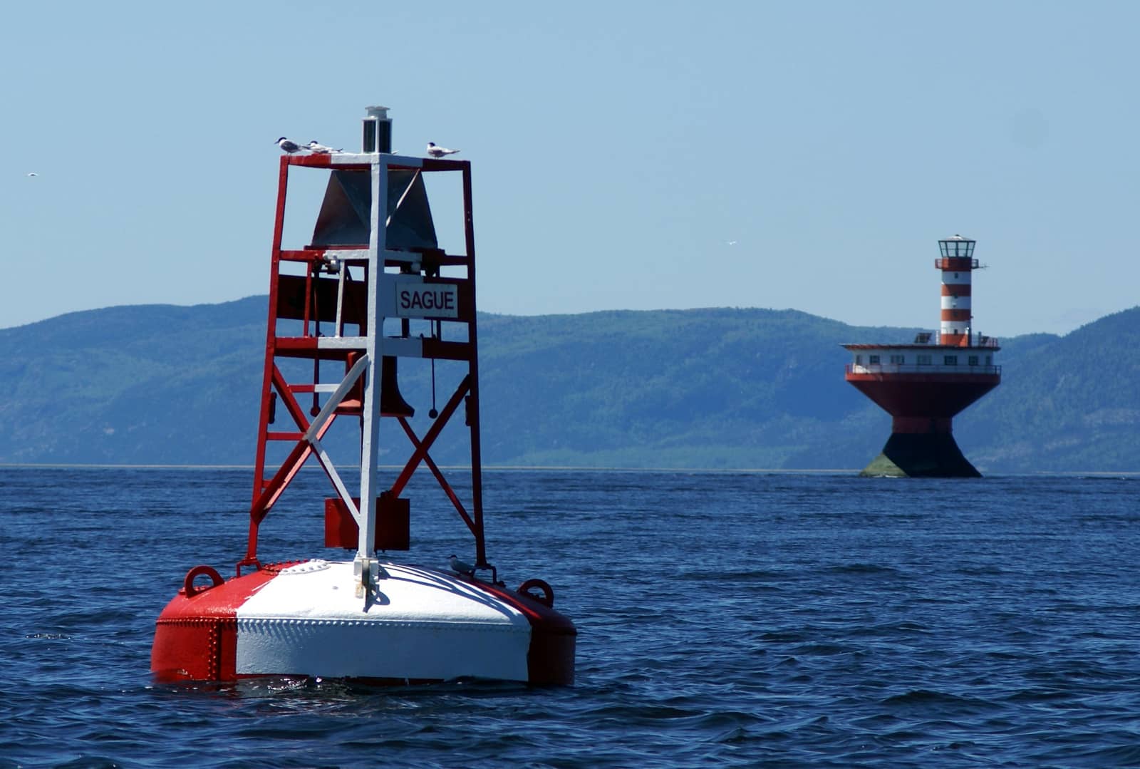
Navigational aids, “navaid” – also known as aid to navigations, “AtoN” –
are special structures such as lighthouses, lightships, beacons, buoys, that are used to enhance safety by providing more opportunities to obtain LOPs.
In contrast: navigational tools including parallel rules, dividers, GPS / Galileo / GLONASS plotters, Radar, compasses, paper charts and sextants.
Lights and marks are prescribed across the world by the International Association of Lighthouse Authorities (IALA). In 1977 this IALA endorsed two maritime buoyage systems putting an end to the 30 odd systems existing at that time.
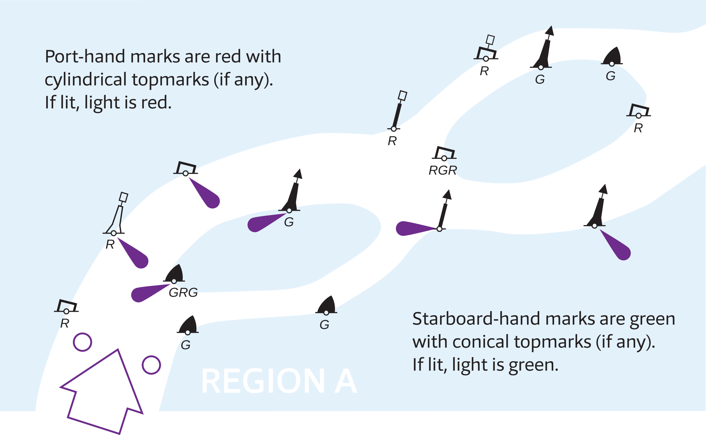
- Region B covers the Americas (incl. Canada), Japan, the Philippines and Korea.
- Region A covers Europe, Australia, New Zealand and the rest of the world.
Fortunately, the differences between these two systems are few. The most striking peculiarity is the direction of buoyage.
All navaids within IALA are distinguished by:
- Shape
- Light
- Colour
- Topmark
Shapes
The standard buoy shapes are cylindrical (can) ![]() , conical (nun)
, conical (nun) ![]() , spherical
, spherical ![]() , pillar
, pillar ![]() and spar
and spar ![]() , but variations occur, e.g. barrel
, but variations occur, e.g. barrel ![]() .
.
Beacons – which are mostly fixed and not floating – have only one elongated and upright shape. The shape of the topmark is essential.
Light identification
During daytime, the identification of aids to navigation is accomplished by observing: location, shape, colour scheme, auxiliary features (sound signals, RACON) or markings (name, number, etc).
Yet, during the night, we use the features of the AtoN's light to both identify it and ascertain its purpose. There are three features to describe the light:
- Colour: either W white, R red, G green, Y yellow, Or Orange or Bu blue.
If no colour is stated in the chart, the default is white.
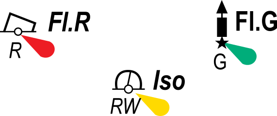
On regular charts a white, red, yellow or green lights will be indicated by , whereas on displays and modern multi-coloured charts in specific colours, such as
  , with the yellow coloured lobe indicating a white light, or if labelled Y, a yellow light.
 - Period: the time in seconds needed for one complete cycle of changes.

For example the marker indicates the 10 second period of the two flashes including 8 seconds of darkness of a “Fl (2) 10s” light.
Except for notably FL (5) 20s , Q (9) 15s and Q (6) + LFL 15s practically all lights have a period of 3 – 10 seconds. - Phase characteristic: the particular pattern of changes within one complete cycle (hence, within one period). Intrinsically, the faster the changes, the more important (or greater) the danger that is covered by the light.
| Abbreviation | Class of light | Illustration / description |
|---|---|---|
| F | Fixed | This light shines with an unblinking and steady intensity and is always on. In this example a yellow fixed light F Y is shown. Often the F is left out, being the default class of light. |
| Occulting: total duration of light longer than total duration of darkness. | ||
| Oc | Single-occulting | Occulting is the opposite of flashing; the light is more on than off. |
| Oc (x) | Group-occulting | This example shows Oc (2). |
| Oc (x+y) | Composite group-occulting | This example shows Oc (2+3). |
| Isophase: duration of light and darkness equal. | ||
| Iso | Isophase | |
| Flashing: less than 50 per minute, and total duration of light shorter than total duration of darkness. | ||
| Fl | Single-flashing | |
| Fl (x) | Group-flashing | This example has three flashes grouped per period: Fl (3) |
| Fl (x+y) | Composite group-flashing | A combination of two patterns in one period. In this example the first 2 flashes followed by the pattern of 3 flashes result in: Fl (2+1) |
| LFl | Long-flashing | This light has one long flash (2 seconds or longer) in a period. |
| Quick: repetition rate of 50 to 79 – usually either 50 or 60 – flashes per minute. | ||
| Q | Continuous quick | |
| Q (x) | Group quick | This example shows a Q (3) light. |
| IQ | Interrupted quick | |
| Very quick: repetition rate of 80 to 159 – usually either 100 or 120 – flashes per minute. | ||
| VQ | Continuous very quick | |
| VQ (x) | Group very quick | This example shows a VQ (3) light. |
| IVQ | Interrupted very quick | |
| Ultra quick: repetition rate of 160 or more – usually either 240 to 300 – flashes per minute. | ||
| UQ | Continuous ultra quick | |
| IUQ | Interrupted ultra quick | |
| Mo (x) | Morse code | A combination of flashes and long-flashes equivalent to Morse code, in this example the letter “A”: Mo (A), which is often used to indicate safe water. |
| F Fl | Fixed and flashing | |
| Al xy | Alternating | In this example Al WG is shown, alternating between green and white. This special purpose light is typically used for special applications requiring the exercise of great caution. |
![]() LFL 10s
LFL 10s
![]() Q(3) G 9s
Q(3) G 9s
![]() Iso 6s
Iso 6s
![]() F Fl Y 5s
F Fl Y 5s
![]() Oc 5s
Oc 5s
![]() Al WR 4s
Al WR 4s
![]() Mo (U) 8s “You are steering a dangerous course”, e.g. near offshore installations.
Mo (U) 8s “You are steering a dangerous course”, e.g. near offshore installations.
List of Lights
All lighted aids to navigation are either major or minor lights, where major lights are used for key navigational points along sea-coasts, channels and harbour and river entrances: nominal range over 10 NM.
When not included in the chart, important details, such as colour, structure, pedestals, range, elevation, of these major lights can be found in a vital reference called Light List or List of Lights.
Examples of such “Light Lists” are NGA (world), USA, France (world), Canada, Admiralty (world), Denmark & Greenland, Norway, Iceland, Brasil, New Zealand, etc.
Minor lights are found within harbours, along channels and rivers, and these are of low to moderate intensity: nominal range less than 10 NM.
The range of lights on buoys are never indicated on the chart (superbuoys are the exception) or in a light list.
On a clear night – and without background lighting – the maximum range that a lit mark will be seen is about 3 NM, but often less than 1 NM.
Small harbour lights will have a nominal range of 1 – 3 NM.
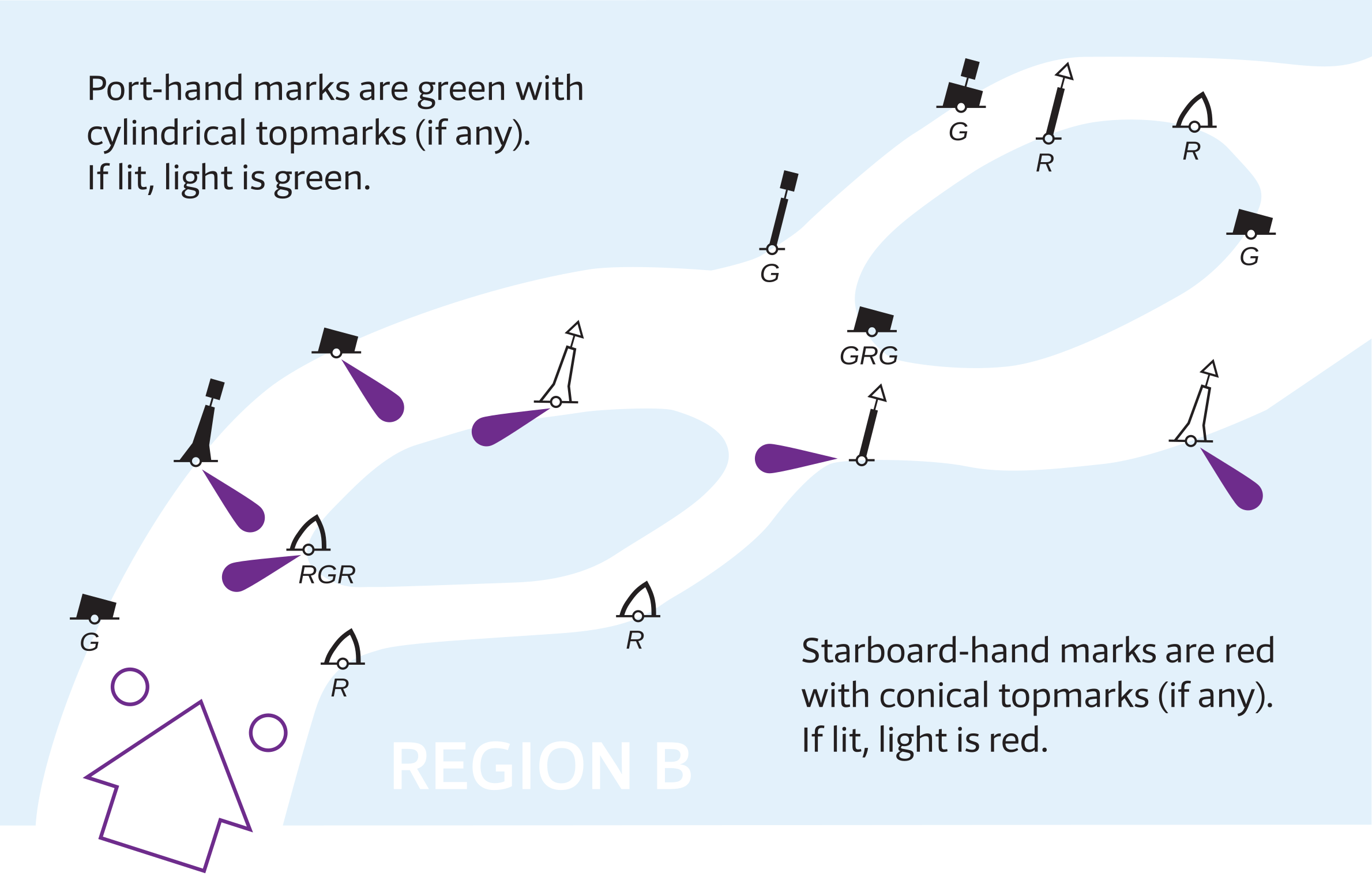
Below, an excerpt from the PDF showing the IALA buoyage system:

in the IALA buoyage system
Mark, buoy, beacon
Strictly, the term “mark” encompasses both beacons ( fixed ) and buoys ( floated ) AtoNs. The latter are far more prevalent; often you can read the term “buoy” as buoy / beacon.
Six types of navigation marks

Port side of the channel, upstream towards the harbour, has red cans with cylindrical topmarks, red lights and even numbers.
Starboard side has green conical shaped buoys with triangular topmarks, green lights and odd numbers.
Lateral marks – direction of buoyage
The location of lateral buoys defines the borders of channels, and their characteristics – such as: colour, shape, light, topmark or odd / even number – indicate the direction of channels, traditionally matching the incoming tide, and on a larger scale, clockwise around landmasses.
- In Region A red buoys mark the port side of the channel when returning from sea; “With aching heart (left side) we leave the open waters”.
Europe, Australia, New Zealand, Rusland, Africa, Middle-East and most of the Far-East. - In Region B green buoys mark the port side of the channel when returning from sea; “Red Right Returning”.
The Americas (incl. Canada), Japan, the Philippines, Taiwan and Korea.
Numbering
If numbered, they will be numbered from seaward with higher numbers nearer to the coast / port.
The protocol is that green buoys have odd numbers and red ones have even numbers.
Lights
If lit, red buoys have red lights and green buoys have green lights.
Their lights can have any calm phase characteristic except for group flashing FL (2+1), which is specifically reserved for the preferred channel buoys.

Sea lions fighting for a preferred spot on a “preferred channel buoy” in Alaska.
Since Region B the Preferred Channel to Port.
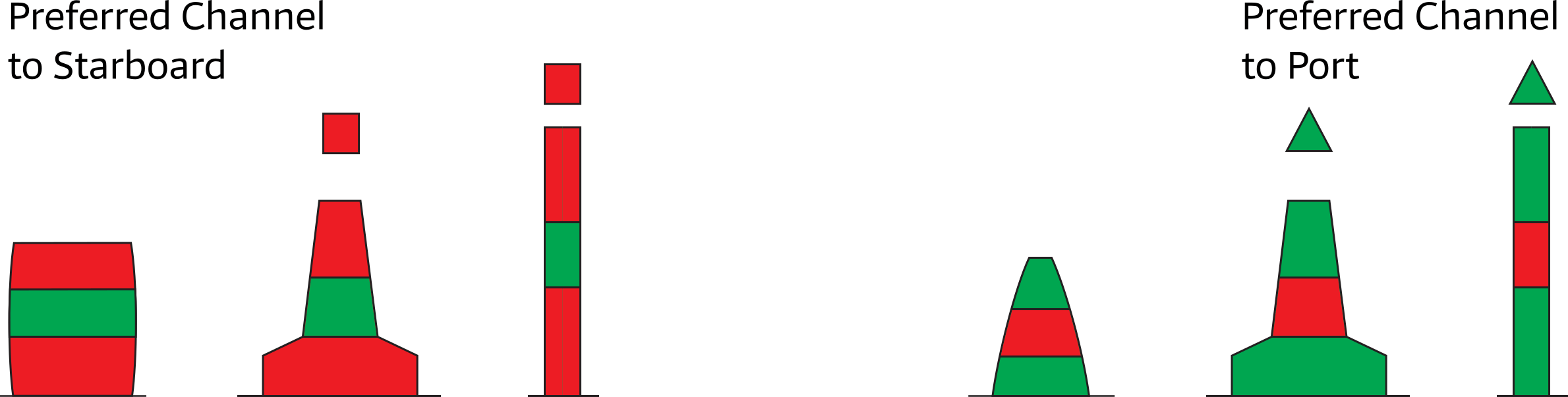
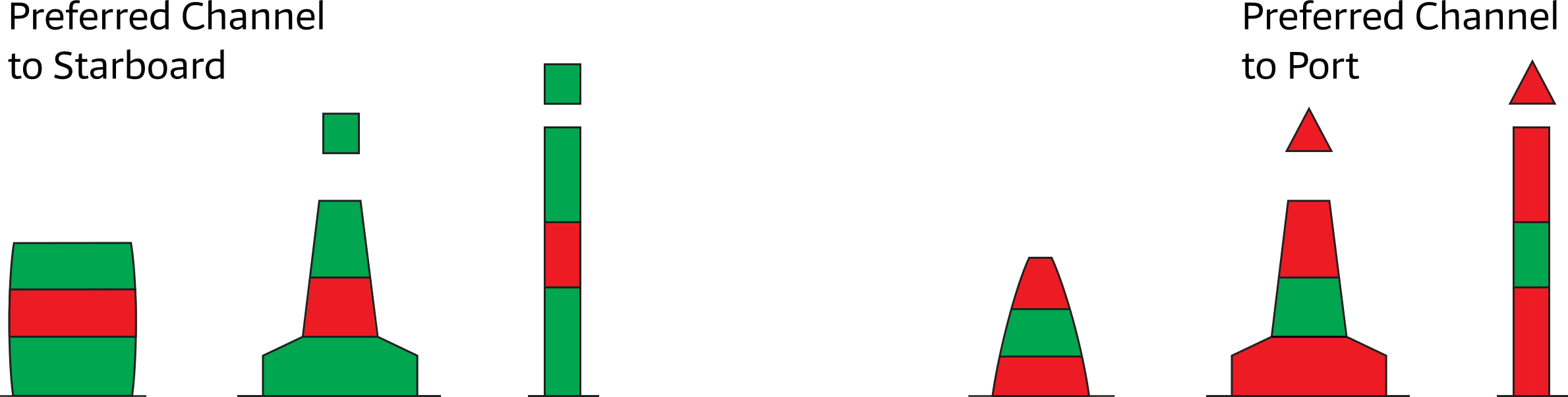
Preferred channel markers
Where a channel splits into a major and a minor channel “preferred channel buoys” may be used, indicating whether the preferred channel is to starboard or to port.
These buoys have both red and green colouring, but the main colour is that for the major channel, with the colouring for the minor channel being only a stripe.
The light phase characteristic is FL (2+1) with the light colour from the major channel.
Shapes
Lateral marks should be of cylindrical and conical shape. However, where they do not rely on a distinctive shape for identification, they should, where practicable, carry the appropriate topmark.
Region A
| Buoyage direction: Green to Starboard. 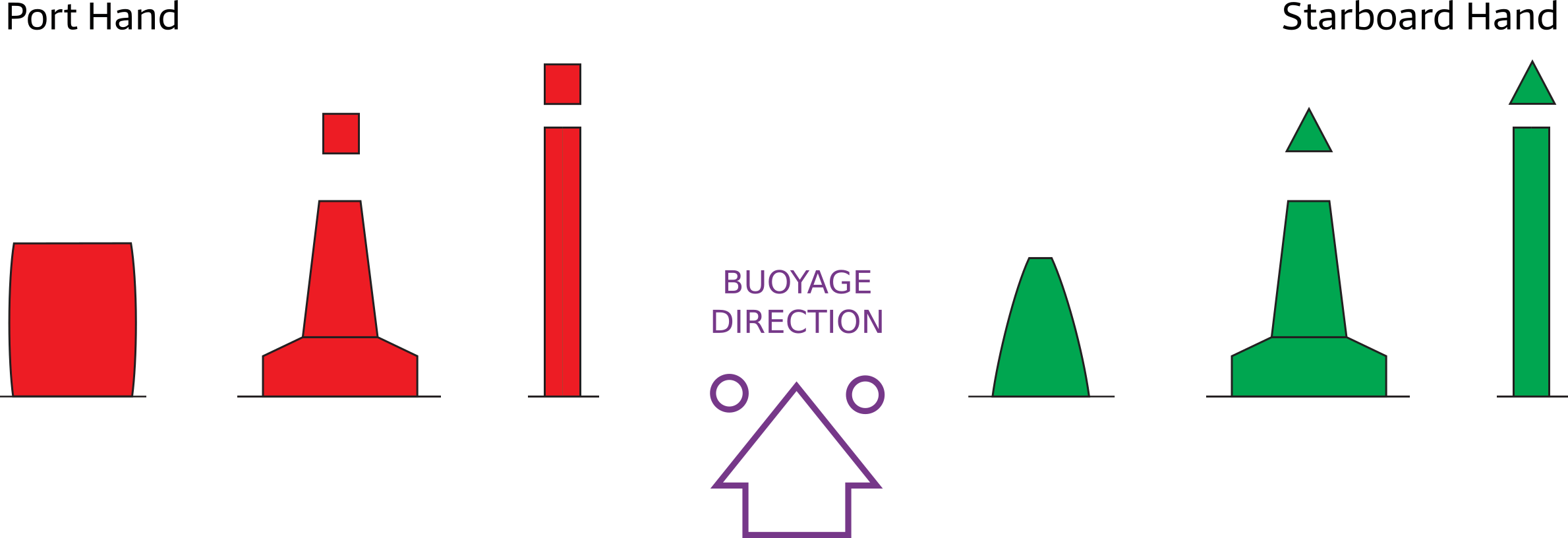
|
||
– and their typical group flash lights. |
||
| Fl (2+1) | ||
|
||
Region B
| Buoyage direction: Red to starboard. 
|
||
– and their typical group flash lights. |
||
| Fl (2+1) | ||
|
||
The following non-lateral marks are all identical in both the A and B Regions.
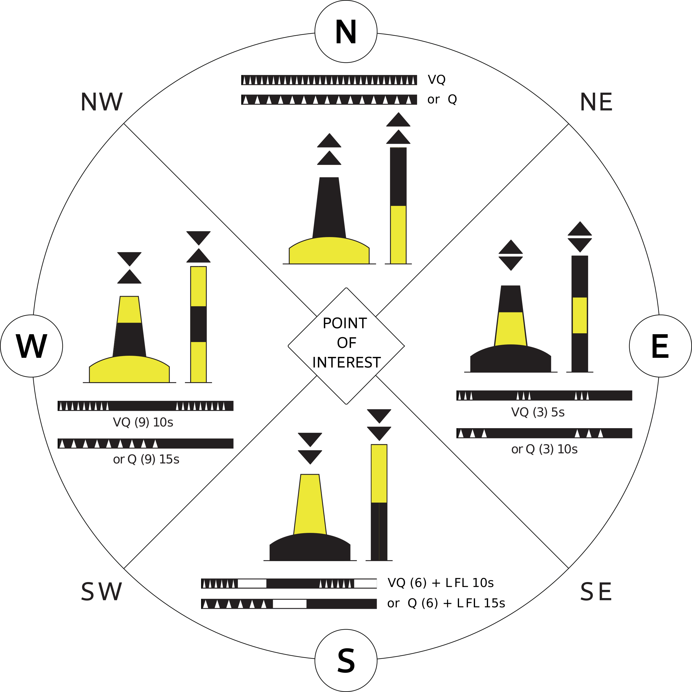
Cardinal marks
The four configurations of cardinal buoys indicate the safe side of a danger with an approximate bearing. For example, the West cardinal buoy has safe water on its West and the danger on its East side.
Body: black and yellow horizontal band(s); pillar or spar.
Topmark: two black cones, with tips pointing towards the black band(s) on the body of the buoy (or beacon), for example for a north cardinal
mark, the black band is at the top.
As with the isolated danger mark, the topmark is not optional.
Lights: white quick flashing or very quick flashing.
Notice the clock face resemblance in light phase characteristics:
3 o'clock is East
6 o'clock is South, plus a long flash
9 o'clock is West.
|
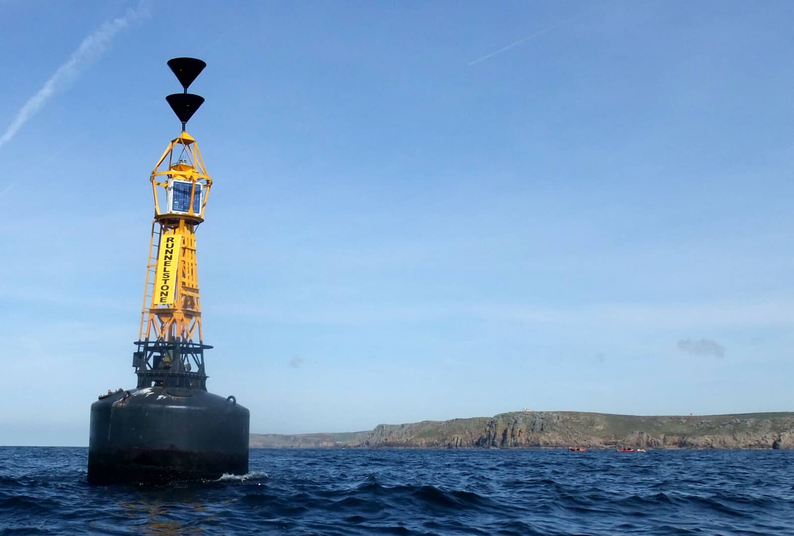
Isolated danger mark
Isolated danger marks are stationed over dangers with navigable water around them.
These buoys are rarely used in sandy regions, such as The Netherlands or Germany.A typical hazard that justifies an “isolated danger mark” atop of it, is a solitary rock.
Contrastingly, cardinal buoys will indicate a direction away from the danger, and are often used for dangers covering larger objects or areas, such as a wreck, shoal or reef.
Body: black with red horizontal band(s); pillar or spar.
Topmark: 2 black spheres, not optional.
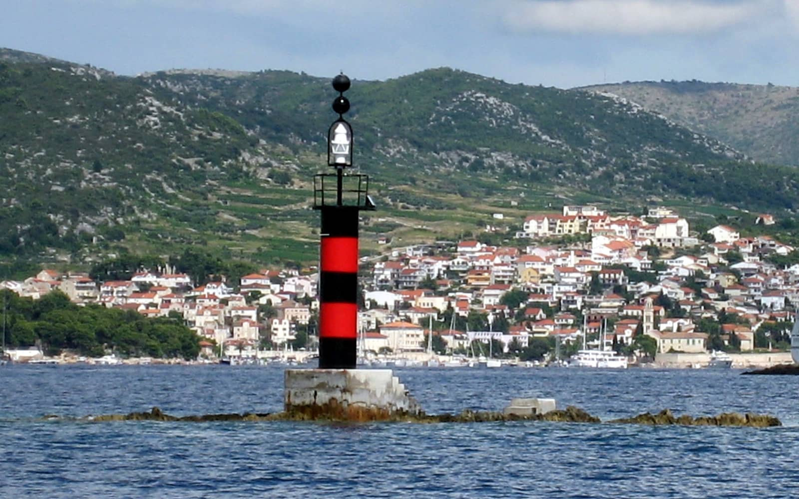
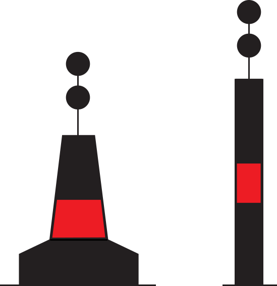
Light: white Fl(2).
![]()
e.g. Fl (2) 8s
can be any period, yet always white.
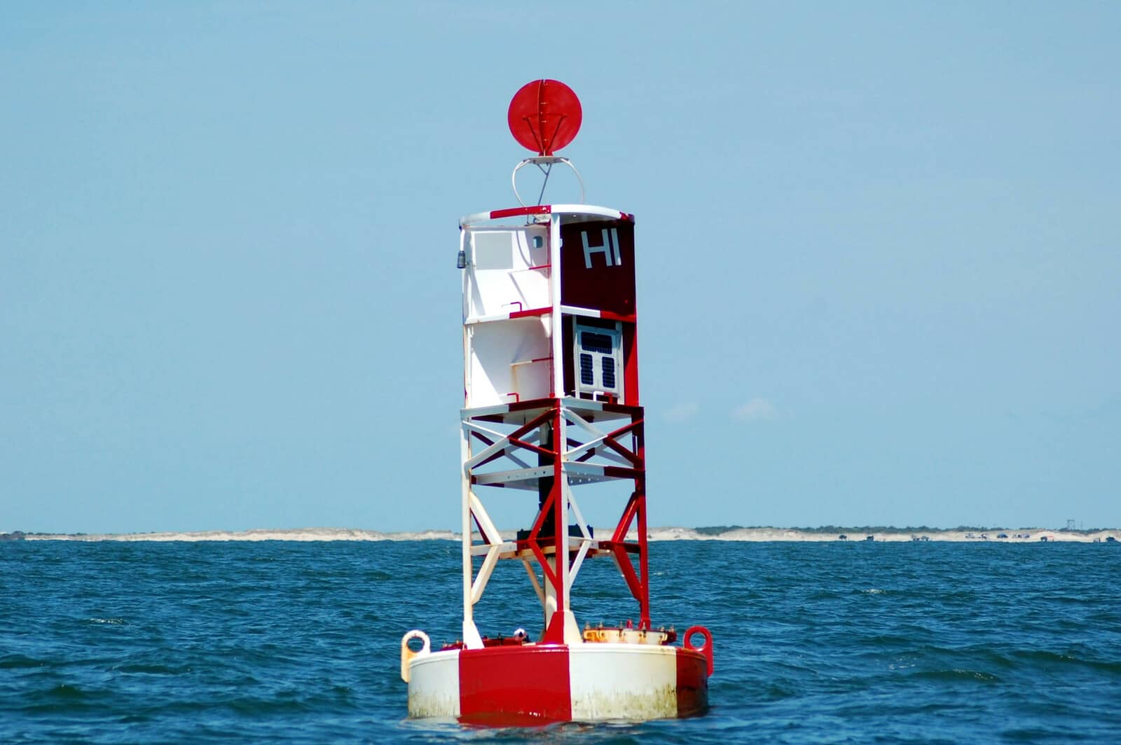
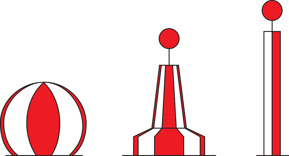
Safe water mark
These marks are used to make landfall and will therefore be to seaward of all other (lateral) buoys, guiding you in.
A second use is to signify the middle or deepest section of a channel.
Body: red and white vertical stripes; pillar, spar, but preferably spherical.
Topmark: single red sphere.
Lights: typically calm and white: Morse A, Iso, Occ or LFl 10s.
New danger mark
After the sinking of the “Tricolor” in the Pas de Calais (Dover Straits) in 2002, several other vessels hit the wreck despite standard radio warnings, three guard ships and a lighted buoy.
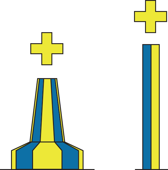
This incident spawned a new type of buoy, the emergency wreck marking buoy, which is placed as close as possible to a new dangerous wreck.
The emergency wreck marking buoy will remain in position until:
- the wreck is well known and has been promulgated in nautical publications;
- the wreck has been fully surveyed and exact details such as position and least depth above the wreck are known; and
- a permanent form of marking of the wreck has been carried out.
Body: yellow and blue vertical stripes; pillar or spar, size dependant on location.
Topmark: a standing / upright yellow cross: a unique, new topmark.
Light: Al Oc Bu Y 3s
Blue 1.0s + 0.5s + Yellow 1.0s + 0.5s = 3.0s
![]()
If multiple buoys are deployed then the lights will be synchronized.
A racon Morse Code “D” and / or
AIS transponder can be used.
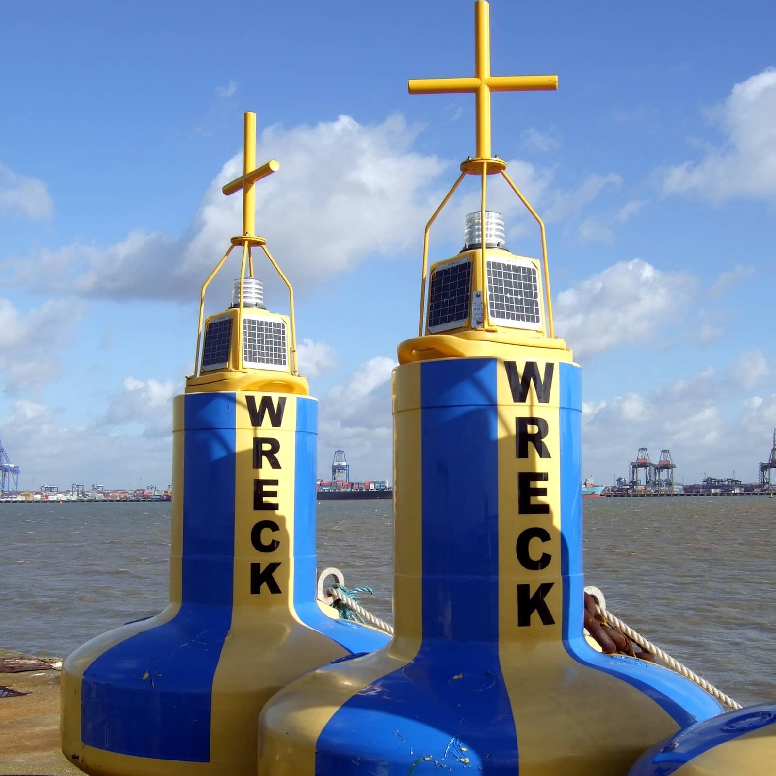
Special mark
Marks used to indicate a special area or feature whose nature may be apparent from reference to a chart or other nautical publication. They are not generally intended to mark channels or obstructions where other marks are more suitable.
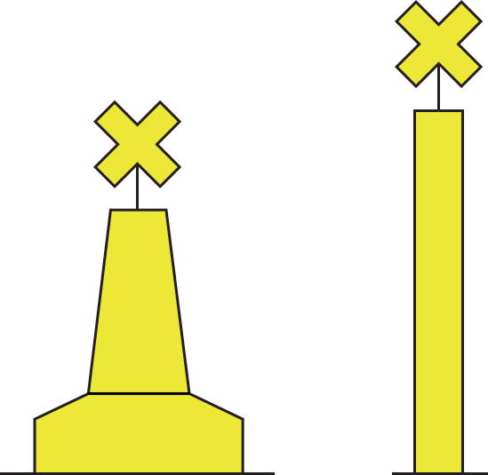
Body: yellow, any shape not conflicting with lateral marks.
Topmark: single yellow " × ” shape
Light: yellow, for instance Fl Y or Fl(4) Y but any rhythm other than those used for white lights on cardinal, isolated danger or safe water marks.
Used for Ocean Data Acquisition Systems (ODAS); cables / pipelines, recreation zones, boundaries (of anchorages), military exercise zones, renewable energy installations and aquaculture.
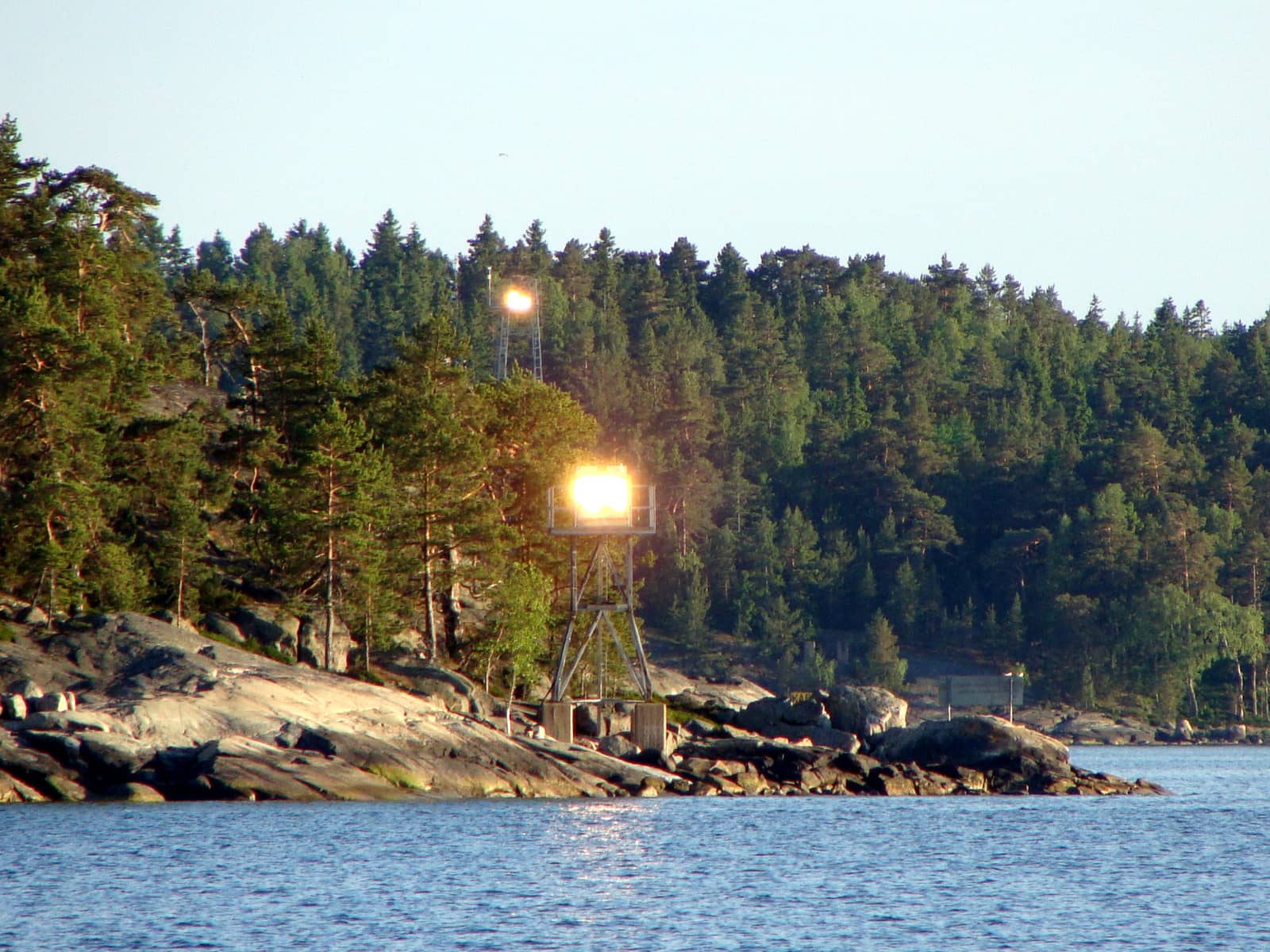
Ranges – leading lines
Leading lights and ranges
A range consists of two or more fixed navigation marks situated some distance apart and at different elevations. If lighted these are conventionally called leading lights since “range” applies to distances as well (dipping range, luminous range, geographic range, etc.).
The shape and colours of the daymarks and the colours and characters of lights are advertised in the “List of Lights".
Too far to port.

When these are in line the ship is on track.
Too far to starboard.
Leading lines
A range provides a leading line for
navigators. When both marks are in
line the observer is on the recommended
track (“on range line”).
Consult the charts for the portion
of channel serviced by the range. The solid line portion indicates the track to be followed; on land and where the water becomes too shallow a dashed line is drawn.
See their chart symbols below.
Explore more examples of man-made or rather inventive rangesranges, as well as natural transit linesnatural transit lines.
So, ranges can be used for:
- finding the recommended track (direction)
- obtaining LOPs (position)
AtoN symbols in the chart
The seafaring nations of the world – members of the International Hydrographic Organisation – agreed in 1982 on an universal set of chart symbols, abbreviations, colours, etc, in order to obtain uniformity and safety, to be used both in the paper nautical chart and in remodelled form in ECDIS the “Electronic Chart Display Information System”.
Some chart symbols come with a line and circle ![]() indicating the precise location, otherwise use the center of the symbol, or its placeholderplaceholder.
indicating the precise location, otherwise use the center of the symbol, or its placeholderplaceholder.
Two distinct types of mark are drawn differently in the chart:
- beacons – commonly fixed to the seabed; drawn upright (even if floated);
- buoys – consisting of a floating object that is usually anchored to a specific location on the sea floor; drawn at an oblique angle and with oblique text (numbering, descriptions of colours and light characteristics).
| Chart symbol | Meaning |
|---|---|
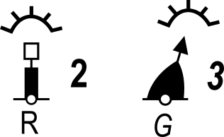
| Major floating light: Light vessel | |
| Major floating light: Superbuoy, e.g. an ODAS buoy | |
| Minor light float | |
| Major light (e.g. lighthouse); minor light (e.g. harbour light) | |
| Green or black buoys (symbols filled black): G = Green ; B = Black | |
| Single coloured buoys other than green and black: Y = Yellow ; R = Red | |
 |
Multiple colours in horizontal bands, the colour sequence is from top ↓ to bottom |
 |
Multiple colours in vertical or diagonal stripes, the darker colour is given first. W = White ; Bu = Blue |
 |
Lighted marks on multicoloured charts, GPS / Galileo / GLONASS displays and chart plotters.
The yellow coloured lobe indicates a White light here! Also note that beacons (here the rightmost symbol with the green light) has an upright G, instead of an oblique G. |
| Chart symbol | Meaning |
|---|---|
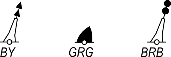
| Most basic beacon symbols | |
| Green or black beacon (symbol filled black). Note the upright G, instead of an oblique G | |
| Coloured beacon other than green and black, the symbol is again filled black so only the shape of the topmark is of navigational significance. | |
| Spar buoy, in this case a safe water mark, otherwise known as a “landfall buoy”. | |
| Beacons with colours and topmarks (examples).
A North cardinal beacon, and a danger beacon. |
|
 |
Red beacon and green buoy with topmark, colour, radar reflector and designation. Red buoys and marks are given even numbers, green buoys and marks are given odd numbers. |
| The black symbol indicates a true radar reflector. Other radar-conspicuous objects – natural or manmade – which are known to give an
unexpectedly strong radar response may be distinguished by the magenta symbol.
Note: Most of the major lighted buoys are standardly equipped with radar reflectors, therefore individual radar reflectors are often not charted. |
|
| Fog: generic sound signal fitted on for example a “pillar buoy” or an “AIS superbuoy”; type of signal not stated.
The sound signal symbol |
|
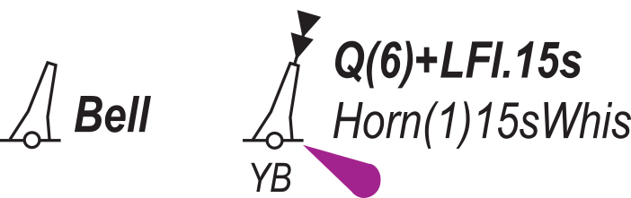 |
Wave-actuated bell buoy, and a lighted buoy with a horn giving a single blast every 15 seconds, in conjunction with a wave-actuated whistle. Other sound options include “Gong”, “Siren”, “Diaphone” (Dia). |
| Chart symbol | Meaning |
|---|---|
| Similar to Leading lights – see below – this leading line is formed by beacons, a solid line is drawn (not merely dashed), indicating the track to be followed.
Sometimes the reciprocal bearing is included, e.g. 270° 90°. |
|
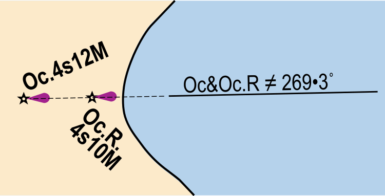 |
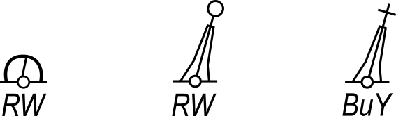
Leading lightsLeading lights (≠ : any two objects in line under each other).
Bearing given in degrees. The lights are often synchronized. The red light has a shorter nominal range (the distance from which the light can be seen): 10 nautical miles.
The solid line is the track to be followed. |
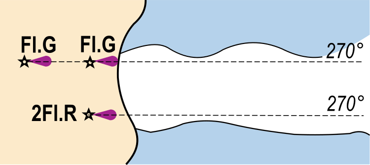 |
Lights in line marking the sides of a channel. Note, instead of solid lines, the dashed lines which are not tracks to be followed. |
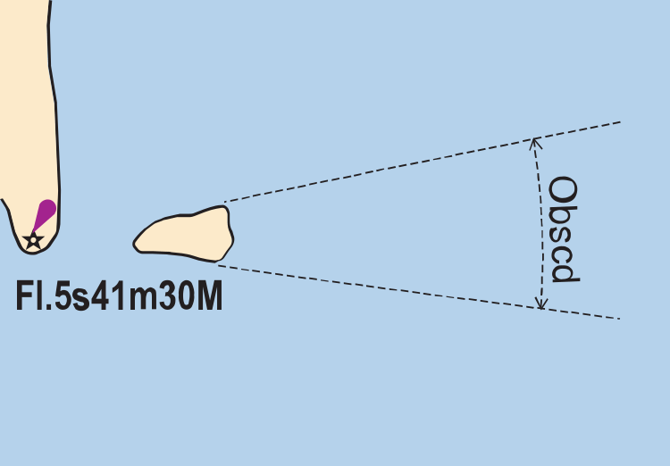 |
All-round light with obscured sector.
Dashed lines mark the sector and are not tracks to be followed. Fl 5s 41m 30M means a flashing white light (one flash every 5 seconds) with an elevation of 41 metres and a nominal range of 30 nautical miles. |
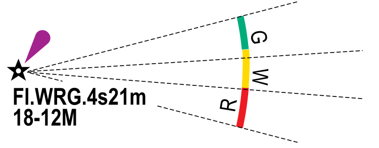 |
Sector light with red, green and white sectors. The elevation is 21 metres (height of the light structure above the chart datum used for elevations). The nominal range of the white light is 18 nautical miles. The range of the green light is 12 nautical miles and the red light is in between. |
| Chart symbol | Meaning |
|---|---|
 |
Symbol showing direction of buoyage (where not obvious). |
 |
Automatic Identification System transmitter. |
 |
Virtual Aid to Navigation with no known IALA-defined function.
A “V-AtoN” does not physically exist but is a digital information object presented on navigational systems. |
 |
Virtual Aid to Navigation with a known IALA-defined function. The topmark indicates the navigational purpose, and this example shows a virtual South cardinal mark. |
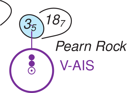 |
The V-AtoN can be offset from, for instance, a submerged danger – as to avoid overlapping that charted feature – with a short magenta “pointer”. |
| Radar transponder beacon, with morse identification, responding within both the 3cm (X) and the 10cm (S) bands, since not specified. | |
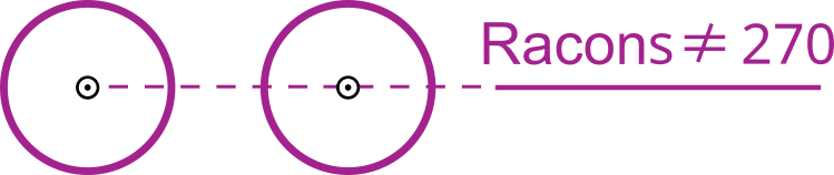 |
Leading radar transponder beacons. (≠ : two RACONS in line under each other). Note, that a solid line is drawn (not merely dashed) to indicate a leading line: a track to be followed. |
Full light description examples
![]()
Fl(3) Class of light: group flashing repeating a group of three flashes
WRG. Colours: white, red, green, exhibiting the different colours in defined sectors
15s Period: the time taken to exhibit one full sequence of 3 flashes and eclipses: 15 seconds
21m Elevation of focal plane above datum: 21 metres
15-11M Nominal ranges: white 15 M, green 11 M, red between 15 and 11 M (nautical miles, NM or M)
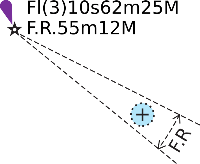
25M and 12M Nominal ranges: white 25 and red 12 nautical miles
When sailing a dangerous course, and within 12 NM, both the white flashing light and the red fixed light will be seen in a vertical line above each other.
Direction lights
Direction (or directional) lights are explained in the Exercises & Answers PDF. These lights a very narrow sector intended to mark a direction to be followed. They are generally used where leading lights cannot be established but serve the same purpose as leading lights.
Visibility of lights
It is important to know at what distance we may (begin to) see a certain light, and when we can expect to lose sight of it, especially when making landfall. Several practical ranges are used to the describe the visibility of lights in navigation:
-
Luminous range – maximum distance at which a given light signal can be seen by the eye of the observer at a
given time, as determined by the meteorological visibility prevailing at that time.
It does not take into account the elevation of the light, observer’s height of eye, or curvature of the earth.
The table below shows that the atmosphere immensely influences the visibility of light travelling through it.
| Code No. | Weather | Distance (m) | Code No. | Weather | Distance (NM) | |
| 0 | Dense fog | Less than 50 | 5 | Haze | 1 – 2 | |
| 1 | Thick fog | 50 – 200 | 6 | Light haze | 2 – 5½ | |
| 2 | Moderate | 200 – 500 | 7 | Clear | 5½ – 11 | |
| 3 | Light fog | 500 – 1000 | 8 | Very clear | 11 – 27 | |
| 4 | Thin fog | 1000 – 2000 | 9 | Exceptionally clear | Over 27 |
The international standards for describing reduced visibility in marine forecasts are as follows:
Very Poor: <0.5 NM
Poor: 0.5 – 2 NM
Moderate: 2 – 5 NM
Good: >5 NM
- Nominal range – the luminous range when the daytime meteorological visibility is 10 NM, which is 74% transmission. Nominal range is generally the figure used in official documentation such
as nautical charts, lists of lights, etc. Nominal range assumes that the light is observed against a dark
background, free of background lighting.
If not stated in the chart, consult the list of lights. The luminous range is the effective nominal range when the atmospheric visibility is not 10 NM. - The geographic range is based on the elevation of the light, the height of eye of the observer and the curvature of the earth.
A higher light means that its horizon is farther away, see distance of horizondistance of horizon.
Similarly, if the observer's height of eye is higher than sea level the light can been seen beyond that geographic range: the dipping rangedipping range.
So, a light – perched on a 70m high cliff – with a geographic range of 20 NM will not be detectable by the human eye (eye height 2m) at a distance of 6 NM, if…
- …the nominal range is just 5 NM, since the light is not very bright.
- …the luminous range is just 5 NM, due to a “Light haze”.
Luminous range diagram
This diagram gives the approximate range at which a light may be sighted, at night, in the meteorological visibility prevailing at the time of observation
The diagram is entered from the top border, using the nominal range stated in the nautical chart or the “list of lights”.
The numbers along the curves represent the estimated meteorological visibility at the time of observation, and those along the left-hand border the luminous range under those conditions.
Example: consider a light of an intensity of 100 000 candelas, which equals a nominal range of about 20 NM.
When the meteorological visibility is 20 NM, the light could be sighted at about 32 miles (navy-coloured line, 1 arrow),
and when 2 NM, at about 6 NM (navy-coloured line, 2 arrows);
given a sufficient elevation and height of eye.
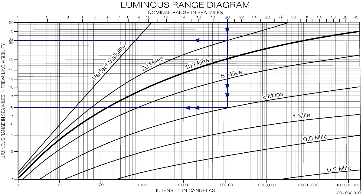
From Nominal range to Luminous range. Download the full-sized, original version for use on board. |
As the scale along the top border is based on a meteorological visibility of 10 NM, the luminous ranges in the prevailing conditions obtained from the bold 10 miles curve will be identical to the nominal range started from the top border.
The diagram can also be used to obtain an approximate meteorological visibility; when, for example, a light of an intensity of 100 000 candelas is sighted at 12 NM, the current meteorological visibility will be about 5 NM.
Caution When using this diagram keep in mind that:
- The ranges obtained are approximate.
- The transparency of the atmosphere is not necessarily consistent between the observer and the light.
- Glare from background lighting will reduce considerably the range at which lights are sighted. A light of 100 000 candelas has a nominal range of 20 NM; with minor background light as from a populated coastline this range will be reduced to about 14 NM, and with major background lighting as from a city or from harbour installations to about 9 NM.
Bottom border: candelas Approximate sighting ranges may be obtained by entering the diagram with the listed intensity divided by 10 for minor background lighting, and by 100 for major background lighting.
Geographic range
A light’s geographic range depends upon the heights of both the light and the observer.
The sum of the observer’s distance to the visible horizon (based on his height of eye) plus the light’s distance to the horizon (based on its elevation) is its geographic range, which is the dipping rangedipping range.
Geographic range = 2.08 × (√Elevation + √Eye height)
For this purpose the formula can be simplified, and solved without a calculator. Assume an opportune standard height of eye of 4 metres as well as rounding 2.08 down to 2.
2 × (√Elevation + 2)
Or if on a smaller yacht, with 3 metres Eye height, you can use √3 = 1.7.
Example with a light elevation of 25 metres:
2 × (5 + 2) = 14 NM
2 × (5 + 1.7) = 13.4 NM with 3 metres Eye height.
Download the geographic range table (PDF) or geographic range table (PNG) or use my online calculator.
See the geographic range table or use my online calculator.
Visible range
When comparing the geographic range with the light’s luminous range, then the lesser of the two ranges is the range at which the light will first be sighted: the visible range.
Plot a visibility arc centered on the light and with a radius equal to the visible range. Extend the vessel’s dead reckoningdead reckoning
track until it intersects the visibility arc.
The bearing from the intersection point to the light is the light’s predicted bearing at first sighting.
Bobbing a light
When first sighting a light, an observer can determine if it is on the horizon by immediately reducing his height of eye. If the light disappears and then reappears when the observer returns to his original height, the light is on the horizon. This process is called “bobbing a light”.
Tide or no Tide…
There will be some judgement involved (luminous range is a rough estimate) resulting in a large margin of error in visible range. Therefore only when light elevation is rather low (<20m), while tidal range is high should it be necessary to include tide.
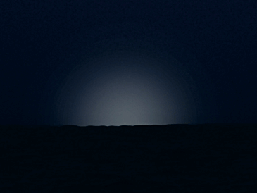
Loom
Because of the limiting factor of the geographic range, most major lights will never be seen from a sailing yacht 20 NM away. Yet, due to atmospheric scattering, it is sometimes possible to take a compass bearing on the loom of the light: its reflection against the clouds. Additionally, it is sometimes even possible to observe a rotating beam of light.
 |
 |
| Loom | Dipping distance / range |
Colours have different ranges
Different coloured lights with equal luminous intensity have different ranges.
White light is the most visible followed by yellow, green and then red.
Therefore, at extreme ranges an “AL WG” can resemble a “Fl W”.
Distance of minor light
The range of a lighted buoy is never indicated, but on a clear night the maximum range is 3 NM, yet often considerably less.
There are 2 visual indicators to determine your distance from a buoy: at about 0.5 NM, the light will rise up from the horizon, and at about 200m, the light will reflect in the surface.
 |
|
 |
| Buoy at less than 3 NM | Buoy at less than 0.5 NM | Buoy at less than 200m |
Glossary
- Loom: the diffused glow observed from a light below the horizon, due to atmospheric scattering of its light rays, usually the undersides of clouds.
- Looming: an apparent elevation of distant terrestial objects by abnormal atmospheric refraction. Because of looming, objects below the horizon are sometimes visible. The opposite is “sinking” during low visibility.
- ENC: the Electronic Navigation Chart.
- ECDIS: the Electronic Chart Display and Information System.
- AIS Aids to Navigation: Automatic Identification System AtoN
- Real AIS AtoN is attached to a physical mark such as a lighthouse or buoy.
- Synthetic AIS AtoN is also associated with a physical mark, but the actual AIS transmitter is in another location.
- Virtual AIS AtoN marks the hazard with the hazard’s coordinates, but there is no physical light, buoy.
- ODAS buoy: Ocean Data Acquisition Systems buoy – means a buoy intended for the collection of data on properties of the ocean. It may be moored or free-floating.
- Aid to Navigation (AtoN) or Navigational aid (NAVAID): any mark, sign, device or system external to vessels that is designed and operated to assist in determination of position, to define a safe course, or to warn of dangers, vessel traffic or obstructions.
- Nominal range is the luminous range when the meteorological visibility is 10 NM, equivalent to a transmission factor of T=0.74.
- Geographical range is the maximum distance at which an object or light from a light source can theoretically be seen by an observer, as limited only by the curvature of the earth, the refraction of the atmosphere, the elevation of the object or light and the height of the observer’s eye.
- Luminous range is the maximum distance at which a given signal light can be seen by the eye of the observer at a given time, as determined by the intensity of the meteorological visibility prevailing at that time. It takes no account of elevation, observer’s height of eye or the curvature of the earth.
Example – a light of an intensity of 500 candelas (nominal range of approx. 8 NM), can be seen up to 12 NM when the meteorological visibility is 20 NM, but will be seen only at 3 NM if the meteorological visibility is 2 NM. - Visible range: the extreme distance at which an object of light can be seen, with current height of eye and current meteorological visibility: the lesser of the luminous and geographic ranges.
- Bobbing a light: quickly lowering the height of eye and raising it again when a navigational light is first sighted to determine if the observer is at the geographic range of the light.
- Luminous range diagram: a diagram used to convert the nominal range of a light to its luminous range under existing conditions.
- Meteorological Optical Codes: ranks from 0 (dense fog : less than 50 metres of visibility) to 9 (exceptionally clear : more than 27 kilometres of visibility).
- Mark, seamark, navigation mark: an artificial or natural object of easily recognizable shape or colour, or both, situated in such a position that it may be identified on a chart. A fixed artificial navigation mark is often called a beacon.
- Light characteristics: the sequence and length of light and dark periods and the colour or colours by which a navigational light is identified.
- Topmark: one of more objects of characteristic shape placed on top of a buoy or beacon to aid in its identification.
- Lateral mark: AtoN intended to mark the sides of a channel or waterway.
- Cardinal marks: black and yellow AtoN intended to show the location of a danger to navigation based on its position relative to the danger using the cardinal points of the compass: North, East, South and West, each with distinctive double-cone topmark variations. If lighted, the Q or VQ group flashes resemble the face of a clock.
- Isolated danger Mark: AtoN marking a danger with clear water all around it; it has a double ball topmark and is black with at least one red band. If lighted its characteristic is Fl(2).
- Sector light: a fixed AtoN that displays a light of different colours and / or rhythms over designated arcs. The colour of the light provides directional information.
- Light sector: as defined by bearings from seaward, the sector in which a navigational light is visible or in which it has a distinctive colour difference from that of adjoining sectors, or in which it is obscured.
- Lighthouse: a tower, or substantial building or structure, erected at a designated geographical location to carry a signal light and provides a significant daymark. It provides a long or medium range light for identification by night.
- Minor light: a light that has nominal range <10 NM. An automatic unmanned light on a fixed structure usually showing low to moderate intensity. Minor lights are established in harbours, along channels, along rivers, and in isolated dangers.
- Major light: a light that has nominal range >10 NM. A light of high intensity and reliability exhibited from a fixed structure (lighthouse) or on marine site (except leading lights). Major lights include primary sea-coast and secondary lights.
- Light List: a detailed list of navigational aids including lighthouses and other lighted navigation aids, unlighted buoys, radiobeacons, daybeacons and racons.
- Landfall: the first sighting, by eye or by radar, of land when approached from seaward.
- Range: two or more objects (leading marks) in line. Such objects are said to be in range. An observer having them in range is said to be “on range line”, or “on track”. Two beacons are frequently positioned together for the specific purpose of forming a range to indicate a safe route or the centerline of a channel.
- Leading line: a straight solid line, drawn through leading marks (a range) on the chart. A ship moving along such line will clear certain dangers or remain in the best channel.
- Leading lights:
also known as range lights in the USA, are a pair of light beacons used in navigation to indicate a safe passage for vessels entering a shallow or dangerous channel, but these may also be used for position fixing.
The lights are a form of leading line so that when they are aligned (brought into transit), with one above the other, they provide a bearing.
The beacons consist of two lights that are separated in distance and elevation, the lower light (front light) is nearest to the observer, the rear light is the farthest to the observer.
In some cases the two beacons are unlighted, in which case they are known as a range in the USA or a transit in the UK. - Lights in line: two or more lights so situated that when observed in transit they define a position: the limit of an area, an alignment used for anchoring, etc. Not to be confused with leading lights, which mark a recommended direction to be followed.
See the next chapter…
- Course overview: goals and introduction
- Positions: latitude, longitude, nautical mile, scale, knots
- Nautical chart: coordinates, positions, courses, chart symbols, projections
- Compass: variation, deviation, true • magnetic • compass courses
- Plotting and piloting: LOPs, (running) fix, dead reckoning, leeway, CTS, CTW, COG
- Advanced piloting: double angle on the bow • four point • special angle fix, distance of horizon, dipping range, vertical sextant angle, radians, estimation of distances
- Astronomical origin of tides: diurnal, semi-diurnal, sysygy, spring, neap, axial tilt Earth, apsidal • nodal precession, declination Moon and Sun, elliptical orbits, lunar nodes
- Tides: tidal height prediction, chart datums, tidal curves, secondary ports
- Tidal streams and currents: diamonds, Course to Steer, Estimated Position
- Aids to navigation: buoys, leading lights, ranges, characteristics, visibility
- Lights and shapes: vessels sailing, anchoring, towing, fishing, NUC, RAM, dredging
Also you can download the exercises + answers PDF ![]()