See the previous chapter…
- Course overview: goals and introduction
- Positions: latitude, longitude, nautical mile, scale, knots
- Nautical chart: coordinates, positions, courses, chart symbols, projections
- Compass: variation, deviation, true • magnetic • compass courses
- Plotting and piloting: LOPs, (running) fix, dead reckoning, leeway, CTS, CTW, COG
- Advanced piloting: double angle on the bow • four point • special angle fix, distance of horizon, dipping range, vertical sextant angle, radians, estimation of distances
- Astronomical origin of tides: diurnal, semi-diurnal, sysygy, spring, neap, axial tilt Earth, apsidal • nodal precession, declination Moon and Sun, elliptical orbits, lunar nodes
- Tides: tidal height prediction, chart datums, tidal curves, secondary ports
- Tidal streams and currents: diamonds, Course to Steer, Estimated Position
- Aids to navigation: buoys, leading lights, ranges, characteristics, visibility
- Lights and shapes: vessels sailing, anchoring, towing, fishing, NUC, RAM, dredging
4 – Plotting and piloting
“Piloting” or “pilotage” is the art of wayfinding using visual fixed points with reference to a nautical chart or publication.
It is considered distinct from, or rather a part of, “navigating“ or “navigation”, which typically refers to wayfinding without frequent and continuous determination of position relative to observed fixed points.
Lines of position
The modern chart shows us positions of many recognizable aids to navigationaids to navigation like churches and lighthouses, which facilitate the approach to a coastal area. This concept originated from a chart by Waghenaer and proved a milestone in the development of European cartography.
His work was called “Spieghel der Zeevaerdt” (Mariner's mirror – 1584),
which included even coastal profiles and tidal information much like the modern chart.
These advancements enable us to find the angle between the north and for example an offshore platform, as seen from our position.
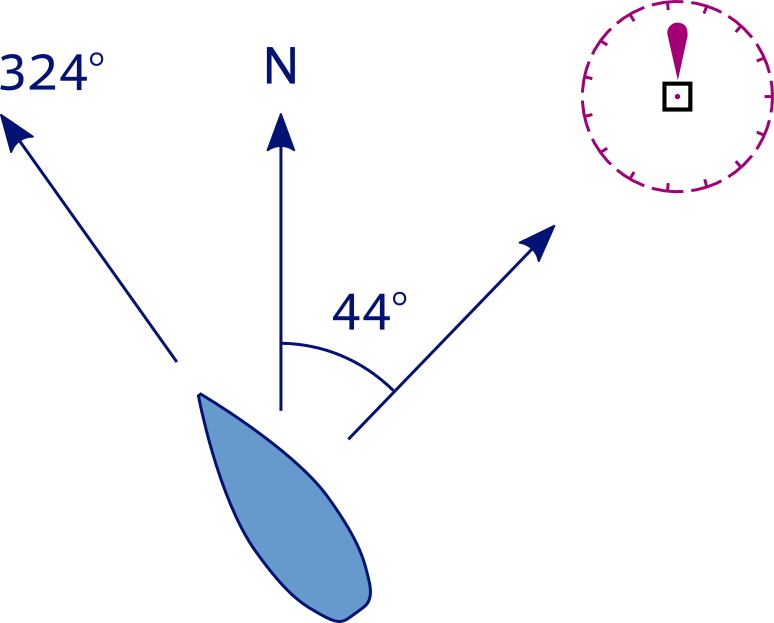
Compass bearing oil rig = 44°
Compass course = 324°
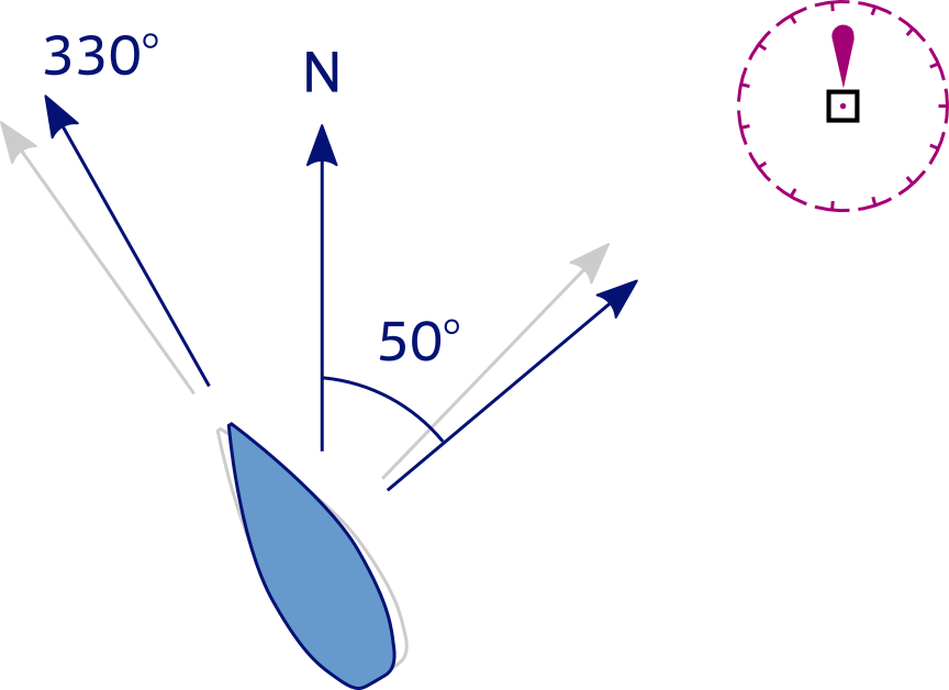
Deviation = +3; Variation = +3
True course = 330°
LOP = 50°
Taking a compass bearing on this oil rig with a steering compass provides us with a “compass course” or “bearing”.
This course first needs correction for both the deviation – according to our current heading, see deviation card or graphdeviation card or graph
– and the variation
before plotting a Line of Position (LOP) on the chart as a true course.
LOP our position is somewhere on this line: 50° towards (or 180° + 50° = 230° eminating from) the oil rig.
Note that with a hand bearing compass only the variation needs to be applied to a bearing; the deviation table refers to errors specifically of the steering compass, see previous chapterprevious chapter.
Ranges
Ranges & Leading lights.
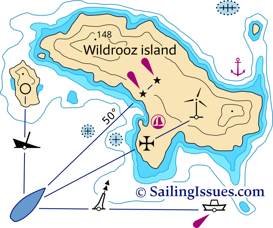
A precise way to obtain a LOP – and without a compass – is to locate two aids to navigation in line. The map of Wildrooz island aboveon the right shows four examples of ranges, each consisting of two aids to navigation:
- visible wreck + silo
- cardinal buoy + light-vessel
- church + wind turbine
- one pair of leading lights
Accuracy is enhanced by:
- more distance between the two landmarks.
- less distance between the vessel and the closest aid to navigation.
One of these four ranges consists of two lights that are intentionally placed to provide an LOP. These pairs of lights are called leading lights producing a leading line: the recommended track.
In depth: ranges and leading linesranges and leading lines.
In this case they indicate the safe approach towards the Wildrooz port by marking the channel between the dangerous rocks along a true course of 50°; often such a range LOP is labeled 50° 230° including the reverse direction.
When looking towards any leading lights, the nearest one will be lower as not to block the signal of the rear light, and
in the middle of the channel both lights will appear vertically “in line".
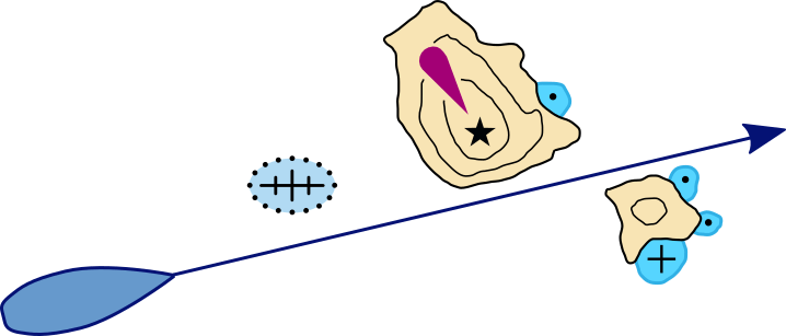
A range without man-made structures.
Transit lines
Even when there are no man-made structures available – which would create a range – a transit line or transit bearing can be found by using natural features such as coastlines and islets.
The example aboveon the left shows a yacht that will avoid the dangerous wreck as long as the islets don't overlap.
Position fix
If two LOPs intersect we can construct a position fix the ship's position on the earth.
Often, however, a triangle occurs when a third LOP is added in the construction. This indicates that there are errors involved in at least one of the bearings taken. In practice, we should consider each LOP as the average bearing in a wider sector of for instance 10°, with 5° on each side of the average bearing, like in the image below.
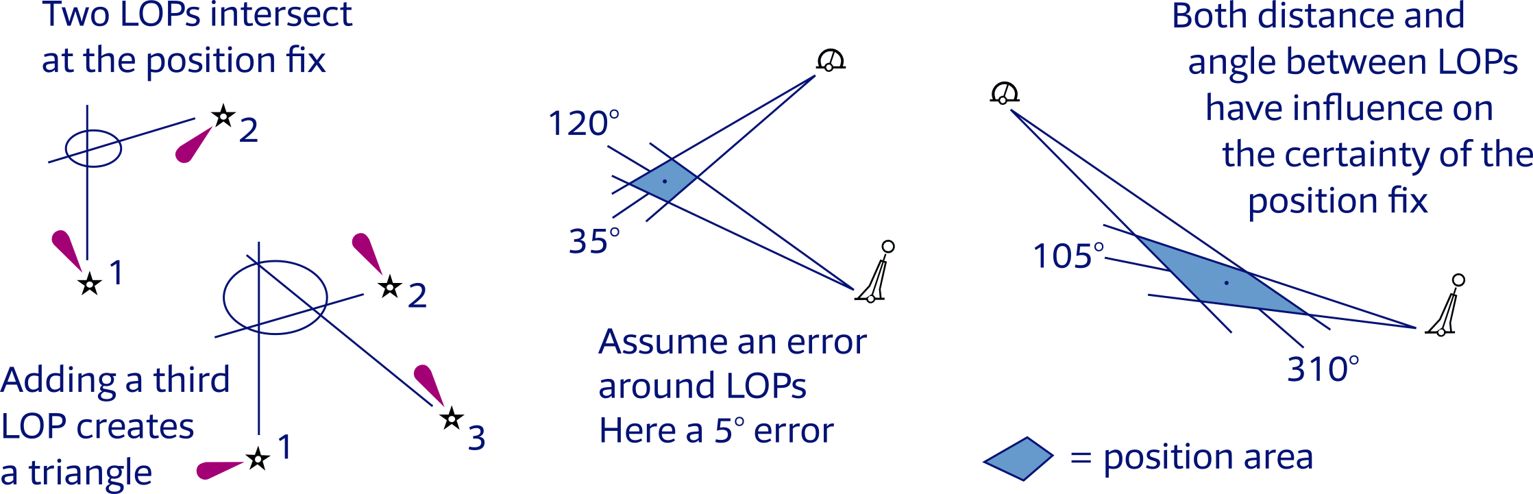
The optimum angular spread is 90° (two objects) or 120° (three objects).
Moreover, bearings on distant objects bring about more uncertainty in our position fix as the error sector widens.
Finally, if moving fast you should not put any time between the bearings.
The next example features a nocturnal landfall on Willemsen Island – you are welcome to visit – but mind the rocks.
The position fix is plotted by taking bearings at two light-vessels as their lights appear over the horizon, as the geographic range of these lights is 14 NM.
The variation is −1° and the ship's compass heading is 190°. If we use our steering compass
for our bearings, we can use the same deviation tabledeviation table
from chapter 3chapter 3. That means a deviation of −4° with which we can calculate (cc + var + dev = tccc + var + dev = tc) the true courses.
If we use our hand held compass it is rarely necessary or possible to correct for deviation – one step less…
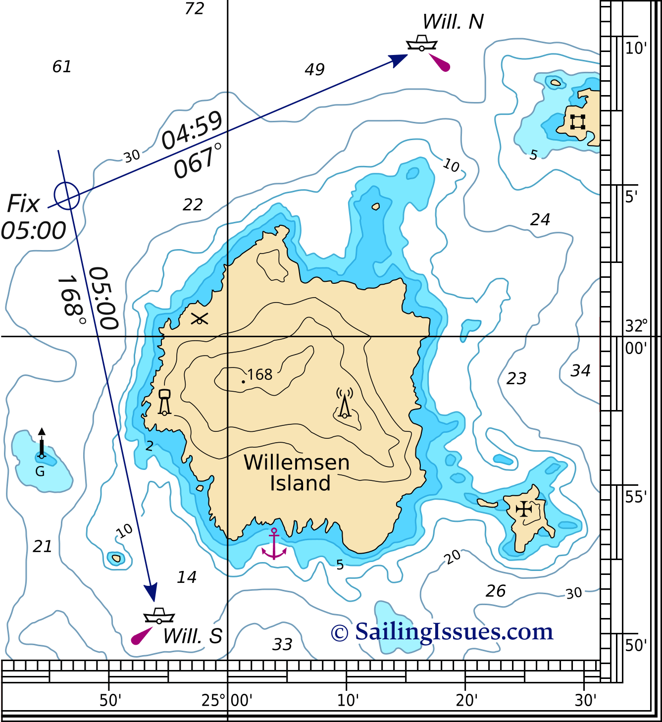
Construction
- Compass bearing on Will. N is 72°
- True course is 67°
- Plot LOP with time + true course
- Compass bearing on Will. S is 173°
- True course is 168°
- Plot LOP with time + true course
- Draw an ellipse where LOPs intersect
- Notate time, label with “Fix ” (or “Fix ”)
- Position is 32° 04,2' N , 24° 46,7' E
Without a third LOP – forming the dreaded triangle – there is the false suggestion of accuracy.
Yet, instrument errors, erroneous identification of an aid to navigation, sloppy plotting, etc. can and will cause navigation errors.
Therefore, if in proximity to e.g. rocksrocks
![]() you should assume to be at the worst possible position, i.e. closest to the navigational hazard.
you should assume to be at the worst possible position, i.e. closest to the navigational hazard.
The lines plotted on the chart are always true courses and these are labeled with true courses by default, e.g. 168° T or simply 168° ; the “ T ” is optional. If labeled with the corresponding magnetic course or compass course add an “M ” or “C ”, respectively.
- A true course corrected for magnetic variation magnetic course use this for hand bearing compass.
- A true course corrected for both magnetic variation and deviation compass course use this for the steering compass.
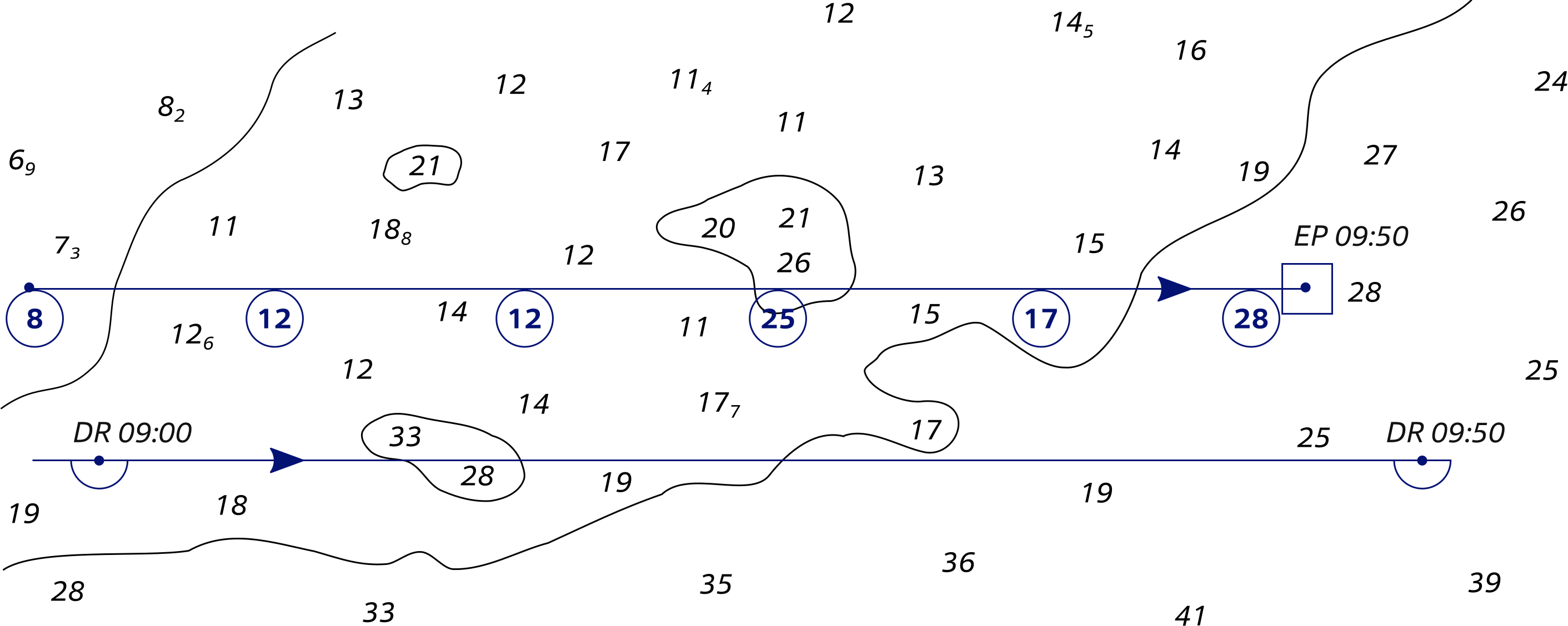
Estimated position
It is sometimes impossible to obtain more than one LOP at a time. To determine the ship's position with one aid to navigation we can use a “ running fix ”, see below when a second LOP becomes available afterwards. In the meantime we aim to plot an estimated position.
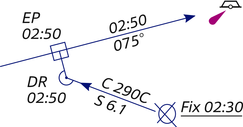
Estimated position plot.
One LOP plus DR position gives EP.
An estimated position is based upon whatever incomplete navigational information is available, such as a single LOP, a series of depth soundings correlated to charted depths, or a visual observation of the surroundings.
In the example an estimated position (EP) is constructed using a single LOP and the ship's dead reckoning position (DR), which is an approximation of the ship's position based on the courses and speeds steered since the last fix.
This is done by drawing a line from the DR position at the coinciding time of the LOP perpendicular to the LOP; the intersection is marked by a square instead of an ellipse.
With this EP construction we improved our position accuracy.
Do not rely on an EP as much as a Fix moreover, a DR position is even less reliable.
Scale of reliability
- Fix
- Running fix
- Estimated position
- DR position
Dead reckoning
Dead reckoning (etymology: deduced reckoning, ded. reckoning) is a technique to determine a ship's approximate position by applying to the last established charted position a vector or series of vectors representing true courses and speed through the water. This means that if we have an earlier fix, we plot from that position our course and “distance travelled since then” and deduce our current position.
Construction DR position
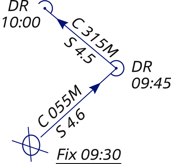
Dead reckoning.
09:30 We start off with a Fix and plot a DR position for 15 minutes later via expected speed through the water and expected true course.
09:45 Our prediction speed and course were correct, so we don't have to charge the DR position. If for instance our average speed was 5 knots we would lengthen the vector accordingly.
10:00 And so on…
Vector labeling
- S = Speed in knots
- C as prefix = Course (default, so optional)
- C as suffix = Compass course for steering compass (corrected for deviation)
- M = Magnetic course for hand bearing compass (no deviation correction)
- T = True course (default, so optional)
Mark with a middle arrowhead, a semi-circle (circular arc) and “DR ”.
Speed and courses for DR plots are always through water and not over ground.
Dead reckoning is also crucial since it provides an approximate position in the future. Each time a fix or running fix is plotted, a vector representing the ordered course and speed originate from it. The direction of this course line represents the ship's course, and the length represents the distance one would expect the ship to travel in a given time. This extrapolation is used as a safety precaution: so, when a predicted DR position places the ship in water 1 metre deep, it should raise an eyebrow…
In the example above the true courses are plotted on the chart, and to assist the helmsperson these course lines are labelled with the corresponding compass courses.
Guidelines for dead reckoning
- Extrapolate your position in the future: plot a new course line from each new fix or running fix (single LOP).
- Choose either a new DR track from an EP (single LOP), or continue along the original DR track.
- Plot a DR position every time course or speed changes.
- Determine your current position: plot a corrected DR position if the predicted course line proofed wrong (e.g. a change in wind meant you sailed less distance and in a different direction), and continue from there.
Non-tidal EP
Note that the EP – discussed in this chapter – disregards any leeway or any tidal flow, combining an LOP with a DR position. Remember that dead reckoning follows essentially a Course through Water (CTW) and is therefore non-tidal.
In the tidal EP section, chapter 8tidal EP section, chapter 8
we will extend this non-tidal EP, marked with a square ![]() , to one that includes the influences of tide and wind. This tidal EP is marked with a triangle
, to one that includes the influences of tide and wind. This tidal EP is marked with a triangle ![]() .
.
Running fix
Under certain circumstances – such as low visibility – only one line of position can be obtained at a time. In this event, a line of position obtained at an earlier time may be advanced to the time of the later LOP.
These two LOPs should not be parallel to each other; remember that the optimal angular spread is 90°. The position obtained is termed a running fix because the ship has “run” a certain distance during the time interval between the two LOPs.
Construction RFix position
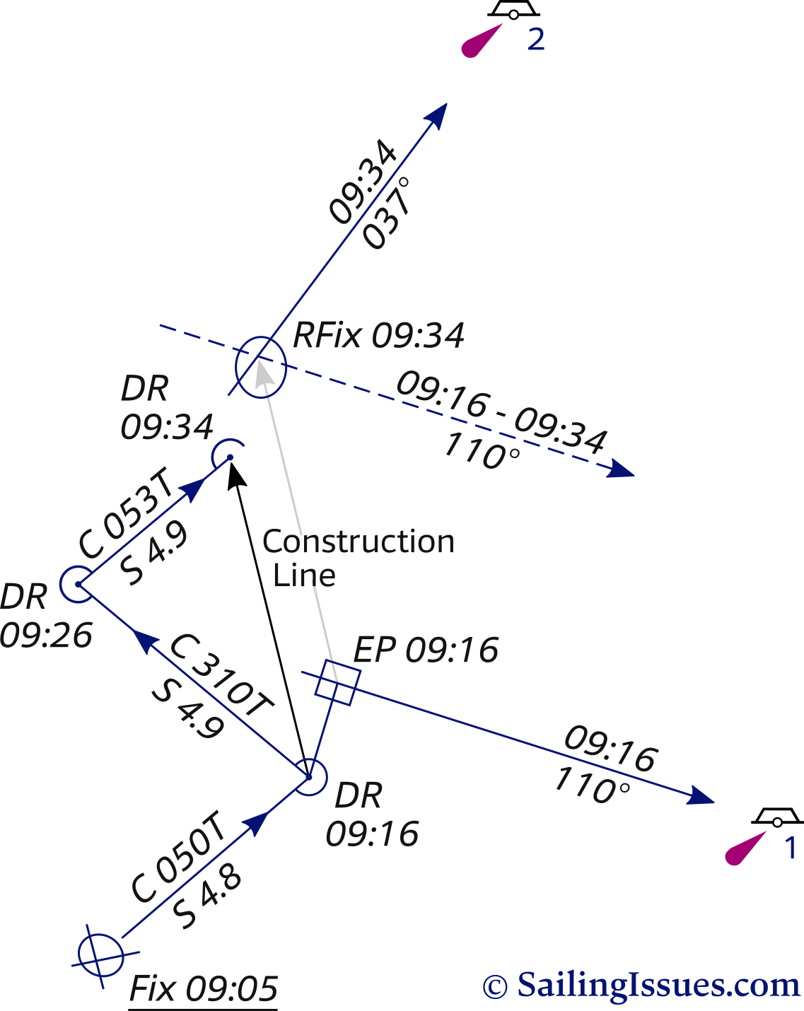
09:16 We obtain a single LOP on superbuoy 1 and plot a coinciding (same time) dead reckoning position. The estimated position is constructed by drawing the shortest line between the DR and the LOP: perpendicular.
09:26 No LOPs at all. We tack and plot a DR position.
09:34 We obtain a LOP on superbuoy 2 and advance the first LOP over a construction line between the two corresponding DR positions.
We use both the line's direction and distance and start from the EP.
To use an LOP obtained at an earlier time, we must advance it to the time of the second LOP. This is done by using the dead reckoning plot. First, we measure the distance between the two DR positions and draw a construction line, next draw a parallel line through the EP.
Now, using the parallel rules we advance the first LOP along this construction line over the distance we measured.
Et voilà, the intersection is our RFix.
Note that if there are no intervening course changes between the two DR positions, it's easiest just to use the course line itself as the construction line.
Yet, if there is an intervening course change, it appears to make our problem harder. Not so since the only DR positions that matter are the two coinciding with the LOPs.
Guidelines for advancing a LOP
- The distance from EP: equal to the distance between the two corresponding DR positions.
- The direction from EP: equal to the direction between the two corresponding DR positions.
- Draw the advanced LOP with a dotted line and notate both times.
- Label the Running Fix position with an ellipse and "RFix" without underlining.
Other RFixes
In the next chapter we will explore three marvellous RFix constructions that use only a single aid to navigation: the doubled angle fixdoubled angle fix, the four point fixfour point fix and the special angle fixspecial angle fix.
Danger bearing
Like dead reckoning, the danger bearing is an important tool to keep the ship out of harm's way.
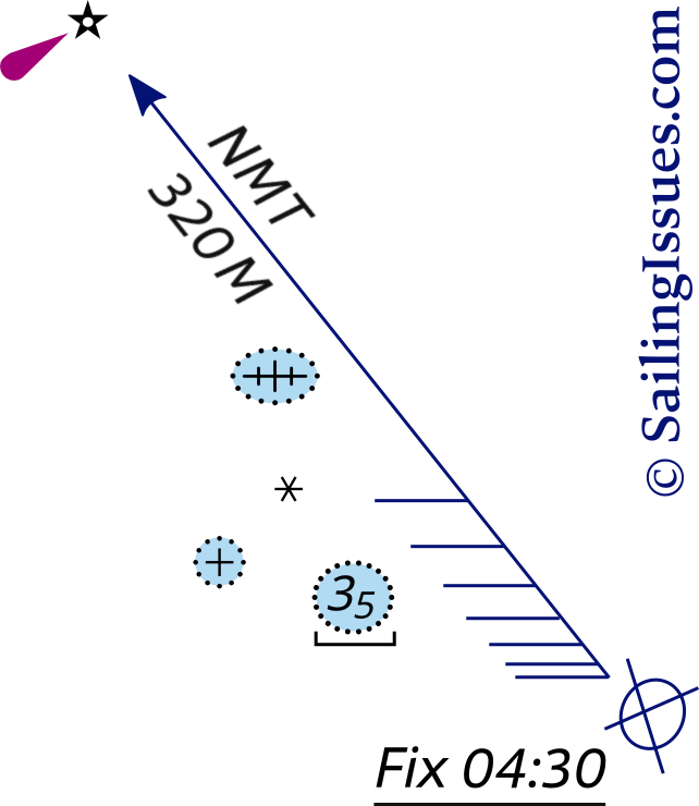
First, the navigator identifies the limits of safe, navigable water and determines a bearing to for instance a major light.
This bearing is marked as No More Than “NMT ” or No Less Than “NLT ”, depending on which side is safe. Hatching is included on the side that is hazardous, along with its compass bearing.
In the example on the right a true course of 325° is plotted, when there is a 5° variation [tc − var = mc = 325 − 5 = 320] , marked by the magnetic coursemagnetic course of 320° [tc = cc + var = 325° = 320° + 5°] , practical for a hand bearing compass that requires no deviation correction.
Were we to see that light at 350° magnetic – which is definitely “More Than” – the rocks and wreck would be between us and the major light; hence NMT instead of NLT. A possible cause could be a (tidal) stream.
Reminder: always plot the true course in the nautical chart.
When a distance – by means of RADAR or sextant – is used instead of a direction, a danger range is plotted much the same way as the danger bearing.
Turn bearing
Similar to the danger bearing and dead reckoning, the turn bearing is constructed on the chart in advance and should likewise be used as a means of anticipation for sailing out of safe waters. The turn bearing is plotted on an appropriate aid to navigation and is marked “TB”. As you pass the object its bearing will slowly change and only when it reaches the turn bearing turn the vessel on her new course.
This type of bearing is also used for selecting an anchorage position or diving position.
Snellius construction
Willebrord Snellius – a 16th century mathematician from Leiden, the Netherlands – became famous for implementing and co-inventing the loxodrome / rhumb line and his method of triangulation.
The Snellius construction was first used to obtain the length of the meridian, and thus the earth's circumference, through measuring the distance between two Dutch cities by famously taking the angles from and to church towers of villages in between.
Nowadays we use the Snellius method to derive our position from three bearings without the use of LOPs, so that deviation and variation are left out → simplifying things.
On top of that, since only relative angles are needed, a sextant can be used to determine the angles between navigation aids at greater distances. Closer in, a compass will suffice as well.
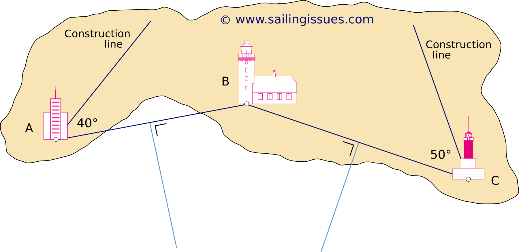
Construction
First steps, see Figure 4.11
- compass bearings are 320° on A; 360° on B; 050° on object C.
- the angle between A and B = 40°.
- the angle between B and C = 50°.
- draw lines from A to B and from B to C.
- add the two light-blue perpendicular bisectors of lines AB and BC.
- draw at object A a construction line 40° inland of line AB.
- draw at object C a second construction line 50° inland of line CB.
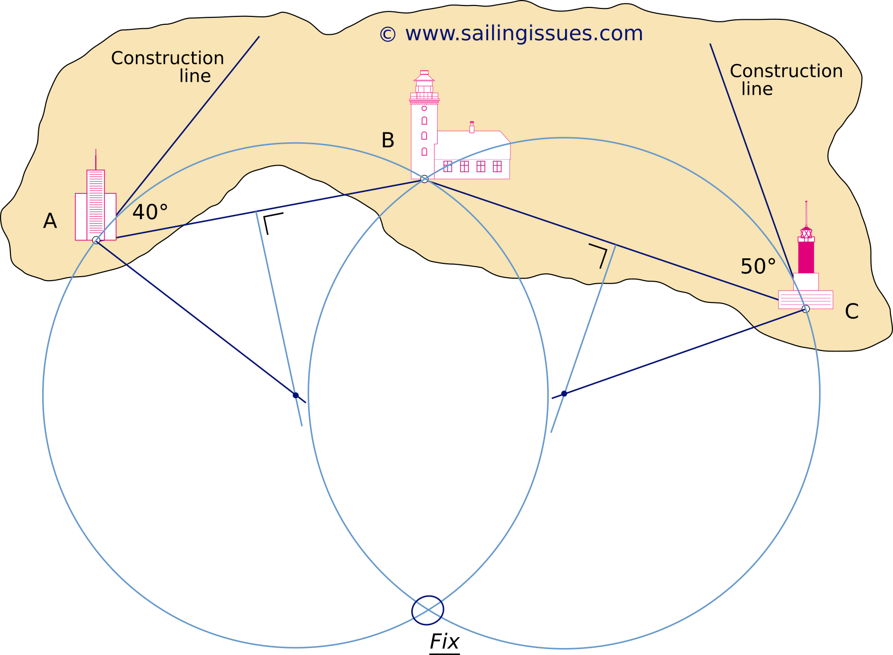
Final steps, see Figure 4.12
- at object A: draw a line perpendicular to the construction line.
- at object C: draw another line perpendicular to the construction line.
- the two intersections with the light-blue lines indicate the centres of two circles.
- finally, draw the first circle using A and B and the second circle using B and C.
- the offshore intersection of the two circle gives us our position fix.
The two advantages:
- both deviation and variation can be left out since the angles (here 40° and 50°) are relative ones.
- a sextant can be used to obtain high precision angles between objects at greater distances, where it would be less precise with compass bearings.
Fix by depth soundings
A series of depth soundings – in this example every 10 minutes – can greatly improve your DR fix, and works best with an irregular or steeply inclined seabed.
Guidelines
- Correct your soundings for tidal height, see chapters 6, 7 and 8. Also note that the depth sounder measures sideways when heeled.
- Copy the DR course line on a transparent sheet, and notate the depths adjacent according to the times of the soundings.
- Move the sheet over the chart to find its best location, and mark as EP.
Due to leeway, currents or other factors the two course lines need not be parallel to or of same length as each other.
Leeway and CTS
Leeway is the amount – usually expressed in degrees – by which a yacht is pushed off course to leeward due to the sideway force of the wind.
This motion away from a desired course is comparable to drift (DFT), yet this is the motion downstream caused by the movement of the water.
Leeway and / or drift can be countered by steering upwind and / or upstream via a Course to Steer (CTS).
The extent of leeway is difficult to determine, but can be estimated by comparing the yacht's centre line i.e. Heading (HDG) with the wake. With experience it gets easier, particularly if you regularly verify, e.g. with AtoNs or satellite navigation, whether your leeway estimate was adequate.
Leeway is at the maximum when a sailing boat is sailing upwind in rough seas and strong winds, but it will also occur when motoring if the wind is strong enough. Factors, which increase leeway are:
- Wind angle – steering close to the wind produces more leeway, e.g. 10°, than sailing a close reach (45 – 90° to the bow), and a beam reach even less. There will be none with the wind astern.
- Wind force – the stronger and gustier the wind, the more leeway. Sailing upwind on a high-performance yacht in a steady 18 kn of wind might result in only 4° leeway, which could double in storm conditions.
- Hull shape and keel shape – most modern cruising yachts should be reefed down early to enable them to sail more upright: a yacht's keel is designed to reduce leeway, so leeway will increase with angle of heel.
- Sea state – high waves increase leeway, even more with waves breaking on the windward side of the vessel. If the yacht is stopped by the force of a wave, leeway can exceed 20°. The rougher and more disturbed the sea, the more leeway.
- Boat speed – leeway increases as boat speed decreases. Vessels travelling at speeds over 25 kn suffer minimal leeway in flat seas on all points of sail, in which case leeway is ignorable. Yet, if this same vessel is hampered by seastate and doing “just” 10 kn then leeway must be considered, certainly when sailing close to the wind.
- Helming skills – novice helmspersons are likely to increase leeway by sailing too close to the wind, then too far off and making the yacht heel excessively. An experienced helmsperson will preserve boat speed with relatively little alteration of course when sailing upwind.
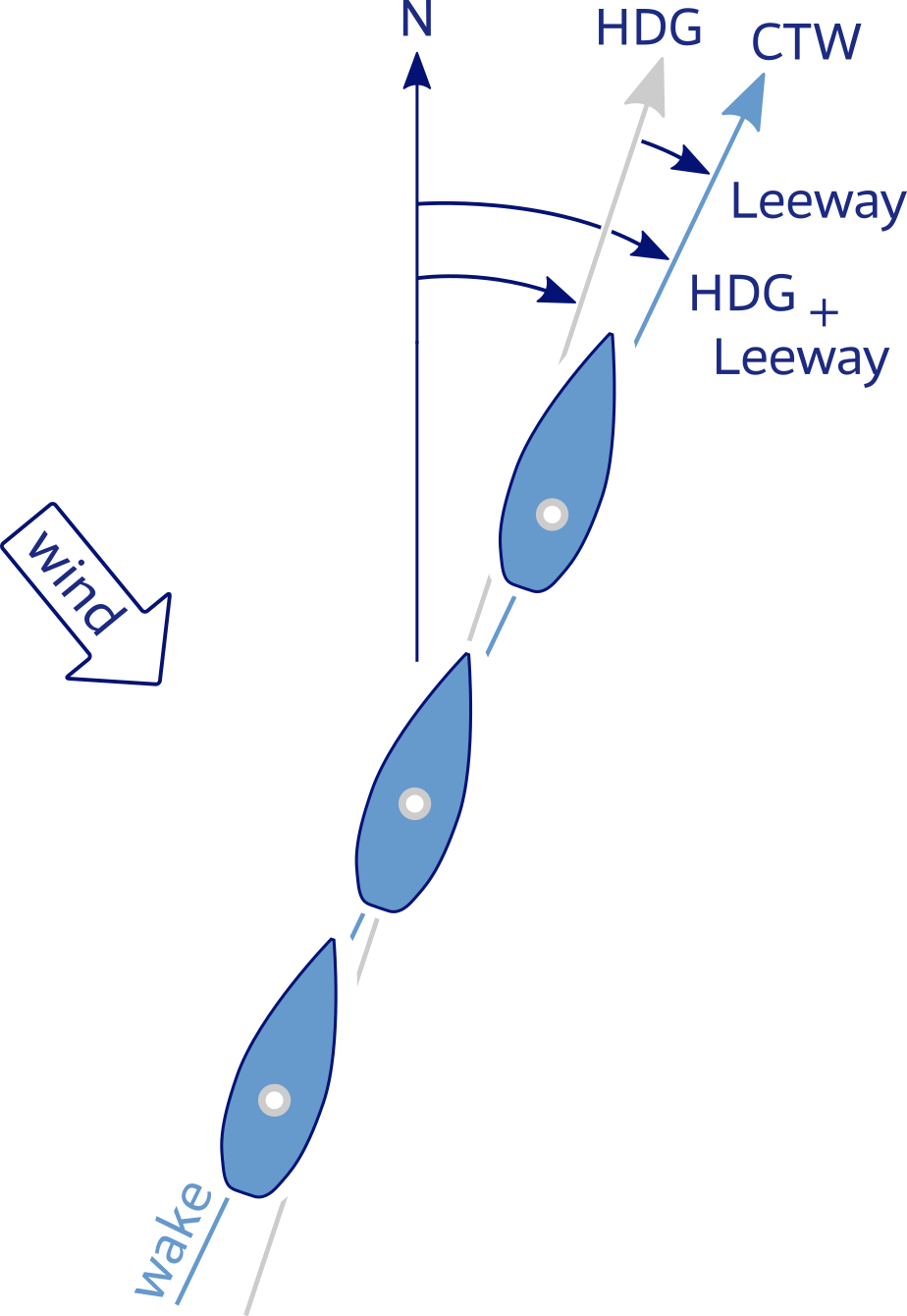
Estimation from the wake, as the yacht is pushed aside by the wind.
Essential terms to counter leeway
- Water Track or Course through Water (CTW) is the direction of the yacht through the water, and is the result of the course steered and any leeway but not tide: Water Track = HDG ± leeway.
Water Track is plotted on the chart using a single arrow at its centre, pointing in the direction of travel. - Course over Ground (COG) is the path of the boat over the ground. Without tidal currents or streams COG is equal to Water Track.
- Course to Steer (CTS) is the required heading of the yacht to achieve an intended COG. The true course must be corrected for leeway, variation and deviation to find the compass course to use at the helm CTS.
Since CTS is a compass course we can use the standard equationequation – re-written and with a correction for leeway – to convert a true course into a compass course:
tc − leeway − var − dev = cc, or apropos:
COG − leeway − var − dev = CTS
The compass rose is clockwise, so:
+ add leeway if the wind is from starboard,
− substract leeway if the wind is from port.
Finding CTS
Correcting for leeway will often alter the vessel's heading by so much that we need to be careful about the order in which leeway, variation and deviation are corrected, or we may end up with the wrong figure for deviation.
To find the Course to Steer, we start with the Water Track from the plot – then corrections should be applied in the following order:
Water Track (CTW) ± leeway − var − dev = CTS
( ± : added or subtracted according to sign)
- first, we correct for leeway sailing the COG towards an intended waypoint.
- second, we correct for variation (found on the chart) to get the magnetic coursemagnetic course. Step 1. and step 2. can typically be switched round.
- last, we correct for deviation (deviation tabledeviation table), as the other two errors may change the compass heading enough to alter the deviation.
An example to illustrate why the order matters:
If the Water Track needs to be 235°T, and there is a 20° of leeway from a NW wind, the yacht needs to steer 255°T.
If the variation is 7°W (−7°), the magnetic coursemagnetic course is 262°M.
Using the deviation tabledeviation table, the deviation for this course is 1°W (−1°) giving a compass course of 263°C.
If the leeway was applied last, the figure for deviation indicated by the table would be 3°W, since 235°T + 7°W = 242°M. And the compass course would be 235° + 7° + 3° + 20° = 265°C. In practice the order of correction only makes a small difference and then only if the leeway is considerable.
Perfectionistic vs pragmatic
On modern vessels the deviation errors can be ≤3°, and correcting for these can be perfectionistic.
Moreover, the amount of leeway can be inconsequential when not sailing upwind.
Both errors should be considered on every leg and passage, but you should also be pragmatic – not inattentive – and consider whether it is possible to safely ignore leeway and / or deviation.
Nevertheless, you must be proficient in correcting for all errors in the right order, because this allows you to:
- navigate safely in circumstances that make sailing difficult: high winds, rough seas, fog, proximity to hazards…
- educate fellow mariners on the underlying principals of navigating safely, without resorting to short-cuts and mnemonics.
- sail any vessel, e.g. charter yachts with significant deviation errors, and in conditions unfamiliar to you.
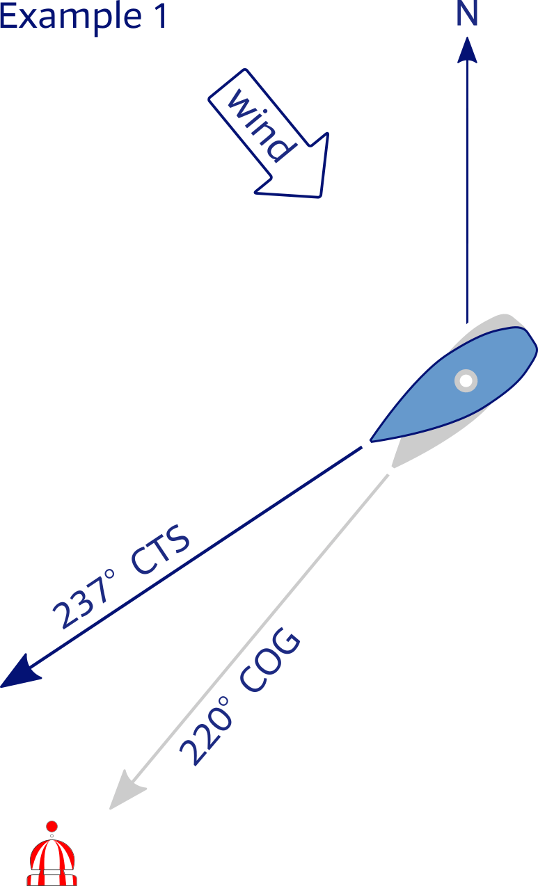
with wind from starboard
Leeway 8°
Variation 5° west
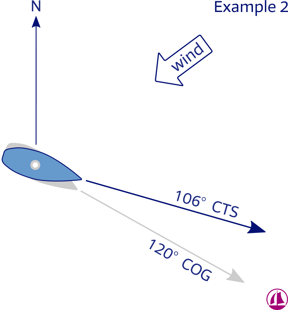
with wind from port
Leeway 11°
Variation 4° east
Example 1 – Correcting for leeway and compass errors, wind from starboard, with no (tidal) currents.
Our COG to approach the safe water buoysafe water buoy is 220°; the local magnetic variation is west 5°, meaning − 5°; and since the wind is from starboard we add leeway + 8°.
Note that COG is equal to Water Track since there is no horizontal movement of water.
We first apply variation and compensate for leeway by steering 8 degrees into the wind:
COG − var + leeway
220° − −5° + 8° = 233°
On this course we find from the deviation table a −4° deviation.
CTS = COG − var + leeway − dev
CTS = 220° − −5° − + 8° − −4°
Our Course to Steer to reach the buoy is therefore 237°.
Example 2 – Correcting for leeway and compass errors, wind from port, with no (tidal) currents.
Our COG to reach the harbour / marina is 120°; the local magnetic variation is east 4°, meaning + 4°; and since the wind is from port we substract leeway − 11°.
We first apply variation and compensate for leeway by steering 11 degrees into the wind:
COG − var − leeway
120° − +4° −11 = 105°
On this course we find from the deviation table a −1° deviation.
CTS = COG − var − leeway − dev
CTS = 120° − +4° − 11° − −1°
Our Course to Steer to reach the buoy is therefore 106°.
International notation
| International notation conventions for plotting on the chart | ||||||
| Fix Visual |
LOP | |||||
| Running Fix | LOP advanced | |||||
| Estimated Position (Tide applied) |
Water Track (CTW) Course & Speed |
|||||
| Estimated Position (Single LOP + DR) |
Tidal vector Set & Drift (Rate) |
|||||
| Dead Reckoning | Track COG |
|||||
| Electronic Fix (GPS) | Electronic Fix (Radar) | |||||
| Waypoint | ||||||
The underline of the Fix label is optional; either Fix or Fix.
Bear in mind that various countries notate an electronic fix by either a ![]() square or a
square or a ![]() triangle or use an alternative strike symbol
triangle or use an alternative strike symbol
![]() for a DR position, and other variations.
for a DR position, and other variations.
LOPs are labeled with the arrowhead at the end, whereas the tidal vector and dead reckoning, COG, CTW course lines / Tracks have the arrowhead(s) in the middle.
Plotting should be done with a soft pencil. Moreover, avoid drawing lines through the chart symbols. This is to prevent damage to the chart when you have to erase the construction.
Learn sailing and navigation via
yacht charters with instruction in Greece.
Glossary
- Line Of Position (LOP): the locus of points along which a ship's position must lie. A minimum of two LOPs are necessary to establish a fix. It is standard practice to use at least three LOPs when obtaining a fix, to guard against the false security, and add accuracy.
- Leading lights or
range lights are a pair of light beacons, forming a leading line, indicating a safe passage for vessels entering a shallow or dangerous channel; and may also be used for position fixing. The beacons consist of two lights that are separated in distance and elevation, so that when they are aligned, with one above the other, they provide a bearing. Leading lights are often illuminated day and night.
If unlit, the beacons are known as a range or a transit. - Transit bearing / range: the method of lining up charted objects to obtain an LOP.
- Position fix: the intersection of various LOPs, labeled as Fix or Fix.
- Cross bearing: LOPs on several navigational aids will obtain a position fix. Remember to use an optimal angular spread: 90° for 2 LOPs or 120° for 3 LOPs.
- Running fix: advancing an earlier LOP to combine it with a current LOP. Make sure to use only the corresponding DR positions; RFix.
- Dead reckoning: determining a position by plotting courses and speeds from a known position – this is good seamanship – will keep the vessel out of harm's way; labeled as DR. It is also used to predict when lights become visible or to determine the set and rate of a current.
Simply put: dead reckoning provides us insight in our present position or our future position.
A dead reckoning position is based on course steered and distance travelled alone; it takes no account of leeway or tidal stream. The DR is the last resort to “navigation”, and when no land or sea marks are in sight to assist in pilotage, just two things are needed.
- The course you have been steering (from the compass).
- The distance travelled (from the log).
Since Dead Reckoning ignores the effects of wind and tide, the accuracy of DR position deteriorates with the passage of time.
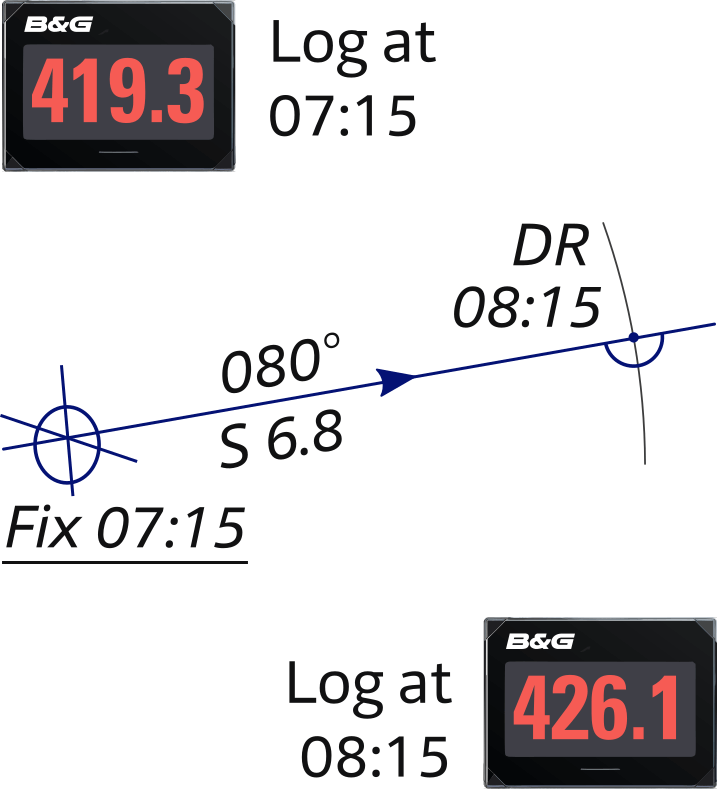
Figure 4.17 shows a DR plot example: the log reading at the time of the 07:15 fix was 419.3 NM, and an hour later it was 426.1, so the distance covered was 6.8 NM.
The boat had been steering 080°, so the 08:15 DR is found by measuring 6.8 NM from the 07:15 position, along the line representing the course steered.
- Estimated position, LOP + DR: combining a corresponding DR position with a single LOP will give an EP position;
 EP.
EP.
This is an improved position based on a DR position. - Estimated position, tide applied: Dead Reckoning with horizontal tidal movement (SET and DFT) applied will give an EP position;
 EP.
EP.
- Snellius construction: a cunning and convenient way to use the angles (via compass or / and ideally by sextant) between three aids to navigation to obtain a position fix. The advantage over a cross bearing is that both magnetic variation and deviation don't need to be taken into account. Furthermore, with a sextant, even at distances beyond 15 NM this method is precise.
- Course versus Track: (C) the term “course" was originally restricted to directions steered or intended to be steered through the water, while the term “track” is a path over ground.
- Course Made Good: (CMG) the resultant direction – a straight line – between any two points on the vessel's track.
For instance: 4 NM east and 4 NM north, would lead to CMG of 045° T.
This is a misnomer in that "courses" are directions steered or intended to be steered through the water. Therefore the term “Track Made Good” (TMG) is more precise and proper. - Track Made Good: (TMG) the single resultant direction from the point of departure to point of arrival at any given time. The use of this term is preferred to the use of the misnomer “Course Made Good.”
- CMG versus COG: CMG (resultant direction) should be distinguished from Course over Ground (COG), which is a dynamic real- time value obtained from satellite navigation.
- Course over Ground (COG) or Track is the direction of the parth over the ground actually followed by a vessel. The preferred term is Track (TR). It is normally a somewhat irregular line.
- Speed Made Good: (SMG) the speed of the vessel achieved over the CMG line / TMG track.
- Speed: (S) the speed of the vessel through the water, in contrast to Speed Over Ground ( SOG ).
- Set: (SET) the direction in which the current is flowing (see chapters 6,7 and 8), current is always expressed in degrees true and always expressed in the direction it is flowing, whereas wind is expressed as where it comes from.
- Drift / Rate: (DFT) the speed (in knots) of the current (see chapters 6,7 and 8).
- Heading: (HDG) the direction in which a vessel is pointing at any given moment. It is expressed as the angular distance relative to north, usually 000° at north, clockwise through 359°, in degrees of either true, magnetic, or compass direction. It is a constantly changing value as a vessel yaws back and forth across the course due to the combined effects of sea, wind, and steering error.
For example, on a sailing yacht the helmsperson may be trying to steer a course of 180°, but the heading one moment is 188° and the next moment it is 074°. The Course remains 180°, which is the intended direction of movement through the water. - Leeway (angle): the leeward motion of a vessel due to wind (and not due water movement); the leeway angle is the angular difference between a vessel's course and the Track (COG) due to the effect of wind in moving a vessel bodily to leeward.
- Course to Steer: CTS is the course to steer to counteract (current and) leeway.
In other words: the course that a vessel should steer in order to arrive at a waypoint, bearing in mind the effects of wind and tide. - Course through Water / Water Track: CTW is the direction of the yacht through the water derived from combining heading and leeway. Water Track = HDG ± leeway.
- Bearing: the direction from one place to another, measured in degrees of angle. When using compass bearings, the reference line is north, so “the lighthouse is on a bearing of 270°” means “the lighthouse is to the west of us.” When using relative bearings, the reference line is the vessel’s centerline. So, dead ahead is 000° and a buoy abeam to starboard (which is nautical terminology for “at 90° to the right when you are facing forward”) bears 090°. Electronic chart plotters provide a continuously updated bearing to an active waypoint.
- Default time: is the 24 hour clock “ship time”, otherwise UTC.
See the next chapter…
- Course overview: goals and introduction
- Positions: latitude, longitude, nautical mile, scale, knots
- Nautical chart: coordinates, positions, courses, chart symbols, projections
- Compass: variation, deviation, true • magnetic • compass courses
- Plotting and piloting: LOPs, (running) fix, dead reckoning, leeway, CTS, CTW, COG
- Advanced piloting: double angle on the bow • four point • special angle fix, distance of horizon, dipping range, vertical sextant angle, radians, estimation of distances
- Astronomical origin of tides: diurnal, semi-diurnal, sysygy, spring, neap, axial tilt Earth, apsidal • nodal precession, declination Moon and Sun, elliptical orbits, lunar nodes
- Tides: tidal height prediction, chart datums, tidal curves, secondary ports
- Tidal streams and currents: diamonds, Course to Steer, Estimated Position
- Aids to navigation: buoys, leading lights, ranges, characteristics, visibility
- Lights and shapes: vessels sailing, anchoring, towing, fishing, NUC, RAM, dredging
Also you can download the exercises + answers PDF ![]()