See the previous chapter…
- Course overview: goals and introduction
- Positions: latitude, longitude, nautical mile, scale, knots
- Nautical chart: coordinates, positions, courses, chart symbols, projections
- Compass: variation, deviation, true • magnetic • compass courses
- Plotting and piloting: LOPs, (running) fix, dead reckoning, leeway, CTS, CTW, COG
- Advanced piloting: double angle on the bow • four point • special angle fix, distance of horizon, dipping range, vertical sextant angle, radians, estimation of distances
- Astronomical origin of tides: diurnal, semi-diurnal, sysygy, spring, neap, axial tilt Earth, apsidal • nodal precession, declination Moon and Sun, elliptical orbits, lunar nodes
- Tides: tidal height prediction, chart datums, tidal curves, secondary ports
- Tidal streams and currents: diamonds, Course to Steer, Estimated Position
- Aids to navigation: buoys, leading lights, ranges, characteristics, visibility
- Lights and shapes: vessels sailing, anchoring, towing, fishing, NUC, RAM, dredging
5 – Plotting and piloting – Advanced
“Mathematical merriment with angles and distances”
In the previous chapter we learned how to plot a “classic” running fixrunning fix
on two separate aids to navigation, AtoNsaids to navigation, AtoNs.
In contrast the following classes of running fixes require only a single aid of navigation, useful when landmarks are scarce, which is often at night when options are limited to those that are lit.
Doubled angle fix – RFix
In the example below the angle of first LOP (α = 30°) on the bow is doubled (β = 60°) when the second LOP is taken, yielding an isosceles triangle: a triangle with two sides of equal length; from Greek roots: “isos” (equal) and “skelos” (leg).
At each LOP the distance readout from the speed log / knotmeter / log instrument is notated, because the distance travelled between the bearings equals the distance from the major light at the time of the second LOP. Note that this instrument shows the mileage / distance travelled through water, and not over ground.
The double(d) angle on the bow fix requires the first bearing to <45° on the bow.
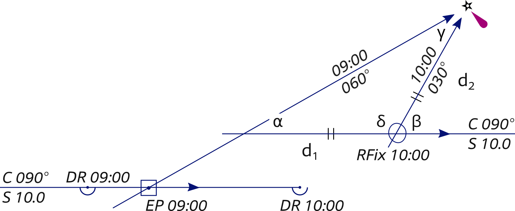
α = 30° and β = 60°
⇒ δ = 120° , ⇒ γ = 30° , ⇒ Isosceles d1 = d2.
The symbol ⇒ means “logically implies that”.
- We start out sailing 90° and an hour before we plotted our expected DR position for 09:00.
- At 09:00 we take the first bearing (α) on the major light,
we notate the log instrument readout,
plot the LOP (here α is 30° on the bow).
As we are further East than expected, we plot an EP.
Lastly, we plot our expected DR position for 10:00 (either from the EP or from the previous DR). - We continue along the course until the angle on the bow is doubled (β is 60°).
- At 10:00 the angle is doubled and we plot the second LOP and read out the log distance: d1 is 10 NM.
- Use this log distance to find the position on the second LOP. Since this is an isosceles triangle ⇒ d2 is also 10 NM.
- Label it with an ellipse and "RFix".
The exercises & answers PDFs
provide further examples of these invaluable triangles.
Four point fix – RFix
A first angle on the bow of 45° gives the ideal situation: the four point fix, so called since 45 degrees equal 4 points on the compass rose 1 point = 11¼° = 360° divided by 32 subcardinals such as NWN.
This is an exceptional “doubled angle on the bow RFix” – with maximum angular spread – creating a right triangle.
For clarity the DR plot is omitted in the example below.
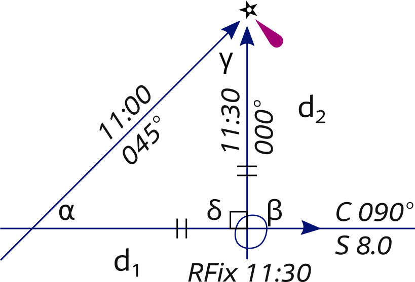
α = 45° and β = 90°
⇒ δ = 90° , ⇒ γ = 45°
⇒ Isosceles d1 = d2
- Start with a bearing with 45° on the bow (α), notate the speed log readout.
- Proceed along the course till the angle on the bow is 90° (β) – again “doubling the angle on the bow” – read the speed log: d1 is 4 NM.
- Use the log distance to find the position on the second LOP. Isosceles right triangle: d2 is also 4 NM.
- Label it with an ellipse and "RFix".
If you continue along your course you can perform – in reverse this time – a second “four point fix” or “doubled angle on the bow fix”, let's call the latter a "halved angle on the stern".
This means 3 LOPs – and a 2nd RFix – for the price of 1 aid to navigation (AtoN).
An important disadvantage of the four point fix over a smaller angle RFix is that the distance (range) of an object is only known until it is abeam. This is of little help in passing at a safe distance, so also apply the following special angle fix.
Special angle fix – RFix
The special angle fix requires the mariner to know some special pairs of angles (α : β) that give the distance travelled between bearings as equal to the distance abeam (perpendicular to the course line or to the fore-and-aft line of the yacht).
A “special pair” consists of two angles on the bow with cotangents that differ by exactly one.
Again, for clarity the DR plot is left out.
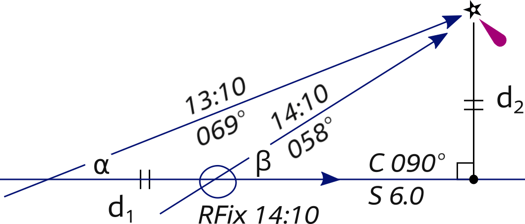
α = 21° and β = 32°
⇒ d1 = d2
In the example above the special pair α = 21° and β = 32° is used; COT (21°) = 2.6 and COT(32°) = 1.6.
- Start with plotting an LOP of 21° on the bow (α), notate the log instrument readout.
- Proceed along the course till the angle on the bow is 32° (β) one hour later, read the speed log: d1 is 6 NM, and plot the second LOP.
- Insightful method:
- Draw from the major light a construction line perpendicular to the 90° course line = 180°.
- Mark the 6 NM distance from the major light on the construction line with a • dot.
- Draw the course line of 90° through the • dot.
- Plot the RFix where it intersects the second LOP.
- Fast method:
- Measure 6 NM along 180° in between the two LOPs, and plot the RFix where it touches the second LOP.
A few practical pairs:
16° : 22° 21° : 32°
25° : 41° 32° : 59°
37° : 72° 40° : 79°
Moreover, all pairs can be found with this calculator:calculator.
Conclusion RFix methods
- Remember: the greater the angular spread the better.
Hence, of these three RFixes the four point fix is the most precise: 45° : 90°. - Yet, the smaller angles will give an earlier prognosis at what distance you will pass an object, so ensure that you apply all RFix methods.
- Keep a very steady compass course in between bearings (LOPs).
- Precision in taking bearings is key, certainly with the special angle fix where an accuracy of ½° is required. A hand-bearing compass usually has a 2° error, GPS compasses are becoming very reliable, even consider compass apps.
- The shorter the distance to the landmark, the better.
- Optionally correct for wind: leewayleeway.
- Correcting for currents: in chapters 66 and 77 and 88, SET and DRIFT (tidal movement) will be applied to the DR track to get an EP
 with tide applied.
Explore the mathematics of isosceles triangle fixesmathematics of isosceles triangle fixes.
Distance of the horizon
On a flat world there would be no difference between the visible and sensible horizon. However, on Earth the visible horizon appears several arc minutes below the sensible horizon due to two opposing effects:
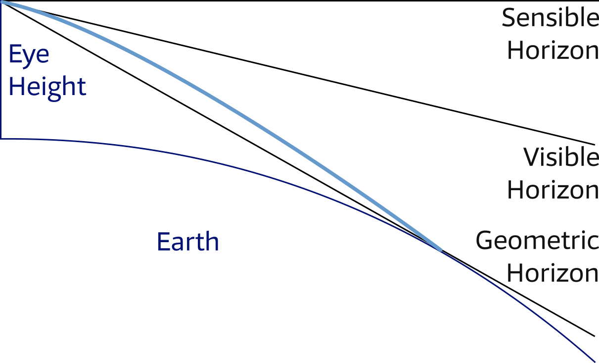
- curvature of the earth's surface
- atmospheric refraction
Atmospheric refraction bends light rays passing along the earth's surface toward the earth. Therefore, the geometrical horizon appears elevated, forming the visible horizon. In other words without an atmosphere the visible horizon would be the same as the geometrical horizon.
The distance of the horizon (visible!) is used for Dipping Ranges and Vertical Sextant beyond the horizon.
The distance (NM) of the visible horizon is a (semi-empirical) and simplified function of Eye Height (Metres):
![]()
Explore the mathematics of horizon distancesmathematics of horizon distances.
Dipping range
The object's elevation – the height (of a light) above CD or Chart Datum – can be found in the chart or other nautical publications such as the essential “List of Lights". Note that in most charts the elevation is referred to a different datum than soundings, e.g. Elevation HW (high water) and Soundings LAT (lowest astronomical tide).
If an object is observed to be just rising above or just dipping below the visible horizon, its distance can be readily calculated using a simple formula.
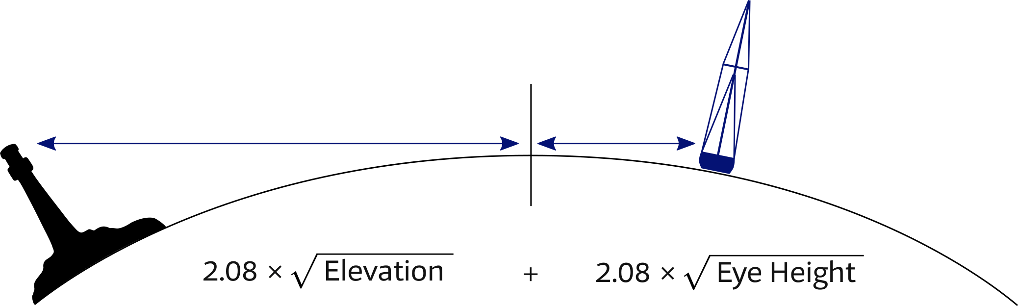
Elevation and Eye Height in metres.
The formula contains the two distances from the visible horizon and can be simplified by the equation: 2.08 × (√Elevation + √Eye height). Many nautical publications contain a table called "distances of the horizon" which can be used instead of the equation.
Use the measured dipping range to plot a Distance LOP or Range LOP in the chart: a circle equal in radius to the measured distance, which is plotted about the navigation aid. Finally, take a bearing on the object to get a second LOP and a position fix.
Establish if and when a light can be sighted: visibility of lightsvisibility of lights.
Experiment with the dipping range calculator belowdipping range calculator. Enter both eye height and elevation in metres, for instance 3.8 and 20.5 respectively…
Instead of calculating you can use the Geographical Range Table, included in the PDFs, to find dipping range.
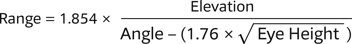
Vertical sextant angle
Similarly, a distance LOP can be obtained by using a sextant to measure the angle (arc) between for instance the light – mind that when close, the light is located below the top – and chart datum of a lighthouse, or any other structure of known elevation.
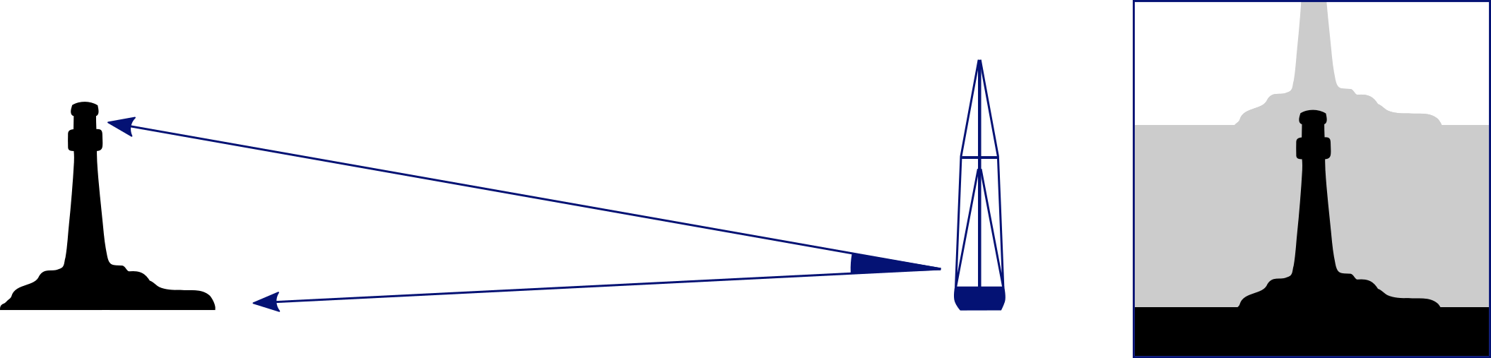
Once the angle is corrected for index error the distance can be found in a table called: "Distances by Vertical Sextant Angle", which is based on the following equation.
Range in NM.
Elevation in metres.
Water Height in metres.
Angle in minutes total.
Guidelines vertical sextant
- The angle in minutes total, thus 1° 12' = 72' total, and corrected for index error
- Elevation in metres; and with a lighthouse on a rock, use: elevation = height rock + height lighthouse!
- Water height in metres above or below chart datum of object.
- Distance or Range in nautical miles.
- Ascertain whether the base of the object is beyond the horizon.
- Corrected angle should be greater than 20'.
Though tables can be used for quick reference, this function is valid for objects higher than normally tabulated.
An example with a lighthouse of 80 metres:
- Measured angle is 1° 19', index error is +6': angle = 73'.
- Let's assume water height at 3 metres above High Water datum.
- Range = 1.854 × (80−3)/73 = 1.96 NM.
The range can be used as a danger bearing.
Together with a compass bearing one object with known elevation results in a position fix.
If more than one vertical sextant angle is combined the optimum angular spread should be maintained.
Angle in minutes total, e.g. 2° 17' is 137' total and also correct for sextant error(s).
Elevation should be corrected for Water Height in metres.
Use the following calculator:vertical sextant angle calculator.
Beyond horizon
Often, the correction for water height can be left out. Though, realizing that the horizon is closer than one might think – e.g. if your Eye Height is 2 metres, the horizon is at just 3 NM – another correction is sometimes needed.
Coastal mountain tops can have bases lying well beyond the horizon. Therefore the aids to navigation, built on these mountains, also have bases beyond the horizon.
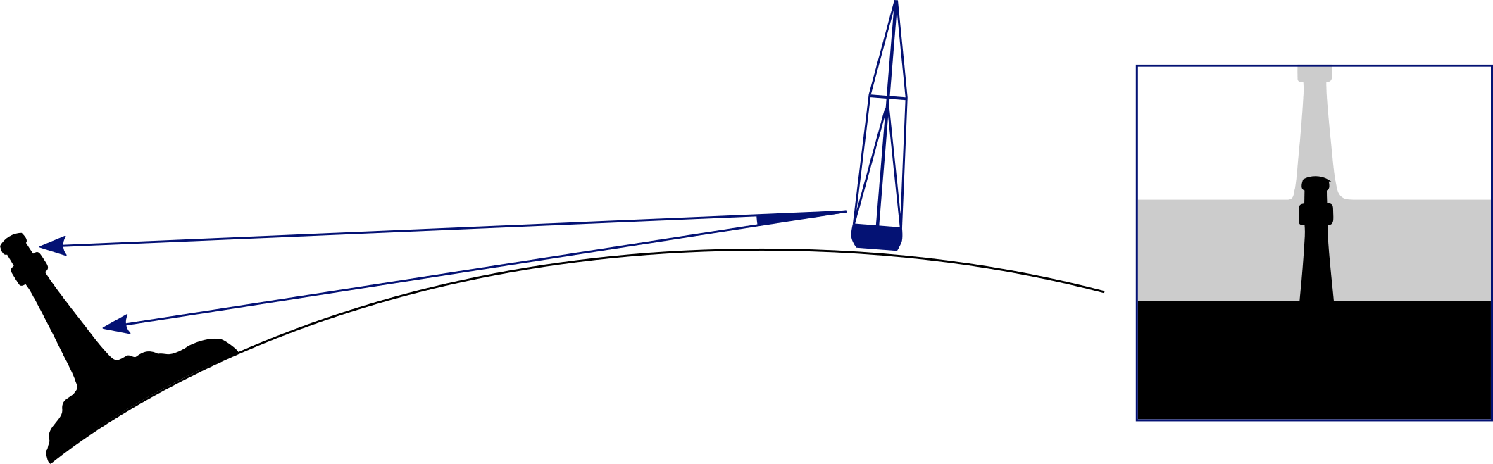
– View through the sextant.
Range in NM.
Elevation in metres.
Angle in minutes total.
This is the equation for finding the distance of an object of known elevation located beyond the horizon.
In the denominator of this equation a compensating factor is included by which the measured angle should be reduced, also see Math of vertical sextant anglesMath of vertical sextant angles.
Use the following calculator:vertical sextant angle dip calculator.
Estimation of distance
Parallax method
The most obvious way to estimate distances is by exploiting our stereo vision to create parallax.
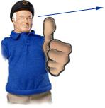
If we sight – first with one eye, then with the other – with an outstretched arm over our thumb, that digit will move across the background, perhaps first crossing a tower and secondly crossing a lighthouse.
The nautical chart might tell that these structures are 300 m apart.
Utilise the ratio of “distance between eye and outstretched arm” / “distance between pupils” – usually 10 : 1 – in which case the objects are roughly 3 kilometres away.
Single eye method
A second method is to use one eye and the dimensions of your thumb, fist or finger(s) as explained in this
video.
Similarly, you will need to take measurements of your own body if you have an arm length of 60 cm, look for a width of 3 cm or 6 cm in your hand, fist or finger(s) to obtain a pragmatic 20 : 1 or 10 : 1 ratio.
Valid for most people: "An object that is three fingers wide is about 10 times as far away as it is wide." This also works vertically.
Measuring angles with your hand
By holding your hand at arm's length, make the various shapes below to approximate the angles between objects (or the edges of a single object) in degrees.
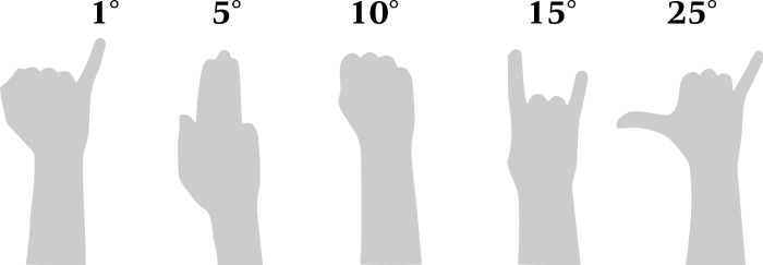
You will need to calibrate for your own bodily dimensions. For most of my crew: 3 fingers = 6°.
How to convert degrees into radians
Essentially, we wish to use these angles to estimate distance, but from a mathematical perspective radians are much prettier and natural than angles in degrees; per definition:
Pi radians are equal to 180 degrees: π rad = 180°
One degree 1° = π / 180° = 0.00556π = 0.01745 rad, and for the smaller angles encountered in navigation we can use the following equation, where thèta (θ) is the angle in radians:
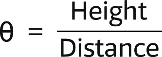
Suitable for nautical navigation since angles will be small.
Range from observable features
The vessel’s range (its “distance off”) from a charted feature gives us a rough LOP, useful when passing outlying dangers, sailing along a coast, or approaching an anchorage.
We can make the following useful observations with naked eye from a yacht’s deck (2 metres height of eye) in good visibility, meaning “more than 5 or 6 NM”.
- Up to 100 m
An individual person can be clearly seen; their eyes appear as dots; architectural details and road signs are easily read. - Up to 250 m
Man or woman, the colour of their skin, clothing and rucksacks can be made out, but facial features cannot; business name boards are readable; window or door is distinctive, but outlines only; van or car still apparent. - Up to 500 m
People appear as a vague shape, thinner at the top; larger farm animals can be recognised, but not dogs or cats; cars are seen as outlines only; trucks can be identified; clocks on towers can be read and standard size flags can be recognised. - Up to 1000 m
Surf, beach and main roads are visible; wider trunks of trees can just be made out, but people ashore are very difficult to spot, only their movement and vehicles; even the biggest signs cannot be read; crew members can be recognised on board other boats against the sky, sail rigging can be seen. - Up to 1 NM (1852 m)
Road traffic and walking adults can barely be seen as moving dots under perfect conditions; chimneys, buildings can be made out, though without much architectural detail; buoys can be identified. - Up to 2 NM (3704 m)
Wide beaches and outlines of conspicuous buildings are apparent, but even moving people or cars cannot be seen; large buoys can be identified with difficulty, at night the navigation lights of boats are becoming visible; 2 NM is the typical range of harbour lights. - Up to 3 NM (5556 m)
This distance is the visual horizon as seen from 2 metre height of eye. Only heavy surf can be discerned; low dunes can still be made out; towers, windmills, grander houses or other unusual buildings require enough contrast from background to be recognised. - Up to 4 NM (7408 m)
Beaches are under the horizon from a yacht’s deck. Forests, dunes and massive buildings can be seen as vague outlines with sufficient contrast; sailboats are minute white dots on the sea, individual floors of large ships can be recognised. - Up to 5.5 NM (~10 km)
Church steeples, radio masts and other high structures are the only person-made features easy to identify.
Estimation with horizon
The image on the right shows us that it is possible to estimate the height of any object that crosses the horizon as seen from our own point of view.
This picture of the “Pigeon Rocks” near Beirut harbour was taken from a eye height of 24 metres; envisage standing on the “crow's nest” or top.
The distance of the visible horizon (>9 NM) is far larger than 24 metres and therefore the lines “eyes—rock_top—horizon” and “sea level” are almost parallel. This means that these rocks have a height of 24 metres as well.

Fact: the part of a rock that lines up with the horizon (and has a base at sea level) is on eye level. If the horizon crosses at a third from the base of the rock: multiply your eye height by three to get its total height.
Finding distance: if we see these rocks over a vertical angle of e.g. 5° = 0.08725 rad, then the range, approximately, is 24 / 0.08725 = 275 metres.
Finally, plot both distance LOP and bearing LOP on the chart to construct an EP. Voilà!
The sextant
Using your sextant to find your latitude position
- Point the sextant at the horizon
- Look through the telescope
- Adjust the index mirror with the index bar until the Sun aligns with the horizon
- Read the angle from the arc
- Take a note of the time
- Consult your celestial table to calculate your position

This instrument is used to determine the angle between the horizon and the Sun, Moon, or a Star (in celestial navigation) or between landmarks, both vertically and horizontally (in coastal navigation).
A sextent consists of a graduated arc, a telescope, and a movable index arm that is allows measuring the angle between two objects.
The mirror on the radial arm can be rotated until the first object is reflected into a half/whole-silvered mirror and superposed on the second object as seen from the telescope.
The angle between the objects is then read from the graduated arc of the sextant.

(a) Horizon in view; fishing trawler added for emphasis of the horizon.
(b) Sun brought into view by mirrors.
(c) Mirrors adjusted so horizon and Sun align.
The horizon mirror is a partial mirror that enables the user to overlay the reflected image from the index mirror, with the horizon viewed directly ahead. It is fixed rigidly to the frame of the sextant.
Horizon mirrors come in two styles: a split mirror and the full semi-silvered mirror.
Top: View with traditional split horizon mirror.
Bottom: View with semi-silvered whole horizon mirror.
Using your sextant to find your longitude position
- You will need to know the precise time using UTC.
- You then need to know local noon, i.e. the time of the highest sextant angle of the Sun at your position: noon sight.
- If your local noon is before UTC noon you are on an eastern longitude. If after UTC noon you are on a western longitude.
- For every four minutes of difference between your local noon and UTC noon your longitude will increase by one degree.
Example: if local noon is 20 minutes after UTC noon (i.e. west).
20/4 = 5 which means your longitude would be 5° W.

“Noon sight navigation requires only the sextant angle of the highest altitude of the Sun at your position on that day, and the exact time of that altitude, known as "local noon".
The sextant in coastal navigation
- Measuring the horizontal angle between two landmarks, e.g. to apply the Snellius constructionSnellius construction.
- Measuring the vertical sextant angle, commonly applied to lighthouses, between the light and the horizon or its base, see Figure 5.17 below, and Figures 5.6 and 5.8.

Left: The view through the telescope with a full semi-silvered horizon mirror; both hemispheres of the horizon mirror are semi-transparent.
Right: The view with a split horizon mirror, where the left or right hemisphere is completely transparent and the other hemisphere is fully silvered.
Yacht charters and learning how to sail
in Greece, Ionian with instruction.
Glossary
- Line Of Position (LOP): The locus of points along which a ship's position must lie. A minimum of two LOP's are necessary to establish a fix. It is standard practice to use at least three LOP's when obtaining a fix, to guard against the possibility of and, in some cases, remove ambiguity.
- Range or Distance LOP: Obtained by using a stadimeter, sextant or radar. A circle equal in radius to the measured distance is plotted about the navigation aid; the ship must be somewhere on this circle.
- Running fix: A position determined by crossing lines of position obtained at different times and advanced or retired to a common time.
- Dead reckoning: Determining a position by plotting courses and speeds from a known position. It is also used to predict when lights become visible or to determine the set and drift of a current. DR positions are drawn in advance to prevent sailing into danger. A DR position will be plotted:
- every hour on the hour;
- at the time of every course change or speed change;
- for the time at which a (running) fix is obtained, also a new course line will be plotted;
- for the time at which a single LOP is obtained;
- and never draw a new course line from an EP position!
- Estimated position: The most probable position of a craft determined from incomplete data or data of questionable accuracy. Such a position might be determined by applying a correction to the dead reckoning position, as for estimated current; by plotting a line of soundings; or by plotting a LOP of questionable accuracy.
- Double angle on the bow: A method of obtaining a running fix by measuring the distance a vessel travels on a steady course while the relative bearing (right or left) of a fixed object doubles. The distance from the object at the time of the second bearing is equal to the run between bearings, neglecting drift.
- Four point fix: A special case of doubling the angle on the bow, in which the first bearing is 45° right or left of the bow. Due to angular spread this is the most precise isosceles fix.
- Special angle fix: A construction using special pairs of relative angles that give the distance travelled between bearings as equal to the navigation aids' range abeam.
- Distance from horizon: The distance measured along the line of sight from a position above the surface of the earth to the visible horizon.
- Sensible horizon: The circle of the celestial sphere formed by the intersection of the celestial sphere and a plane through the eye of the observer, and perpendicular to the zenith-nadir line.
- Visible horizon: The line where Earth and sky appear to meet. If there were no terrestrial refraction, visible and geometrical horizons would coincide. Also called: “apparent horizon”.
- Geometrical horizon: Originally, the celestial horizon; now more commonly the intersection of the celestial sphere and an infinite number of straight lines tangent to the earth's surface and radiating from the eye of the observer.
- Dipping range or Geographic range: The maximum distance at which the curvature of the earth and terrestrial refraction permit an aid to navigation to be seen from a particular height of eye (without regard to the luminous intensity of the light).
- Elevation: The height of the light above its chart datum in contrast to the height of the structure itself.
- Chart Datum: Officially: Chart Sounding Datum: An arbitrary reference plane to which both heights of tides and water depths are expressed on a chart. In the same chart heights can be related to other datums than depths.
- Vertical sextant angle: The method of using the subtended angle of a vertical object to find its range.
- Index error: In a marine sextant the index error is primarily due to lack of parallelism of the index mirror and the horizon glass at zero reading. A positive index error is subtracted and a negative index error is added.
- Estimation with horizon: Estimation of heights using the horizon: All tops crossing the horizon and with bases at sea level are on eye level.
Mathematics: isosceles triangle fixesMathematics: isosceles triangle fixes
Mathematics: horizon distancesMathematics: horizon distances
Mathematics: sextant anglesMathematics: sextant angles
See the next chapter…
- Course overview: goals and introduction
- Positions: latitude, longitude, nautical mile, scale, knots
- Nautical chart: coordinates, positions, courses, chart symbols, projections
- Compass: variation, deviation, true • magnetic • compass courses
- Plotting and piloting: LOPs, (running) fix, dead reckoning, leeway, CTS, CTW, COG
- Advanced piloting: double angle on the bow • four point • special angle fix, distance of horizon, dipping range, vertical sextant angle, radians, estimation of distances
- Astronomical origin of tides: diurnal, semi-diurnal, sysygy, spring, neap, axial tilt Earth, apsidal • nodal precession, declination Moon and Sun, elliptical orbits, lunar nodes
- Tides: tidal height prediction, chart datums, tidal curves, secondary ports
- Tidal streams and currents: diamonds, Course to Steer, Estimated Position
- Aids to navigation: buoys, leading lights, ranges, characteristics, visibility
- Lights and shapes: vessels sailing, anchoring, towing, fishing, NUC, RAM, dredging
Also you can download the exercises + answers PDF ![]()